Imaging lens
a technology of imaging and lens, applied in the field of imaging lenses, can solve the problems of difficult correction of aberrations at the peripheral area, inability to obtain excellent optical performance, etc., and achieve the effects of low profile, high resolution and low f-number
- Summary
- Abstract
- Description
- Claims
- Application Information
AI Technical Summary
Benefits of technology
Problems solved by technology
Method used
Image


Examples
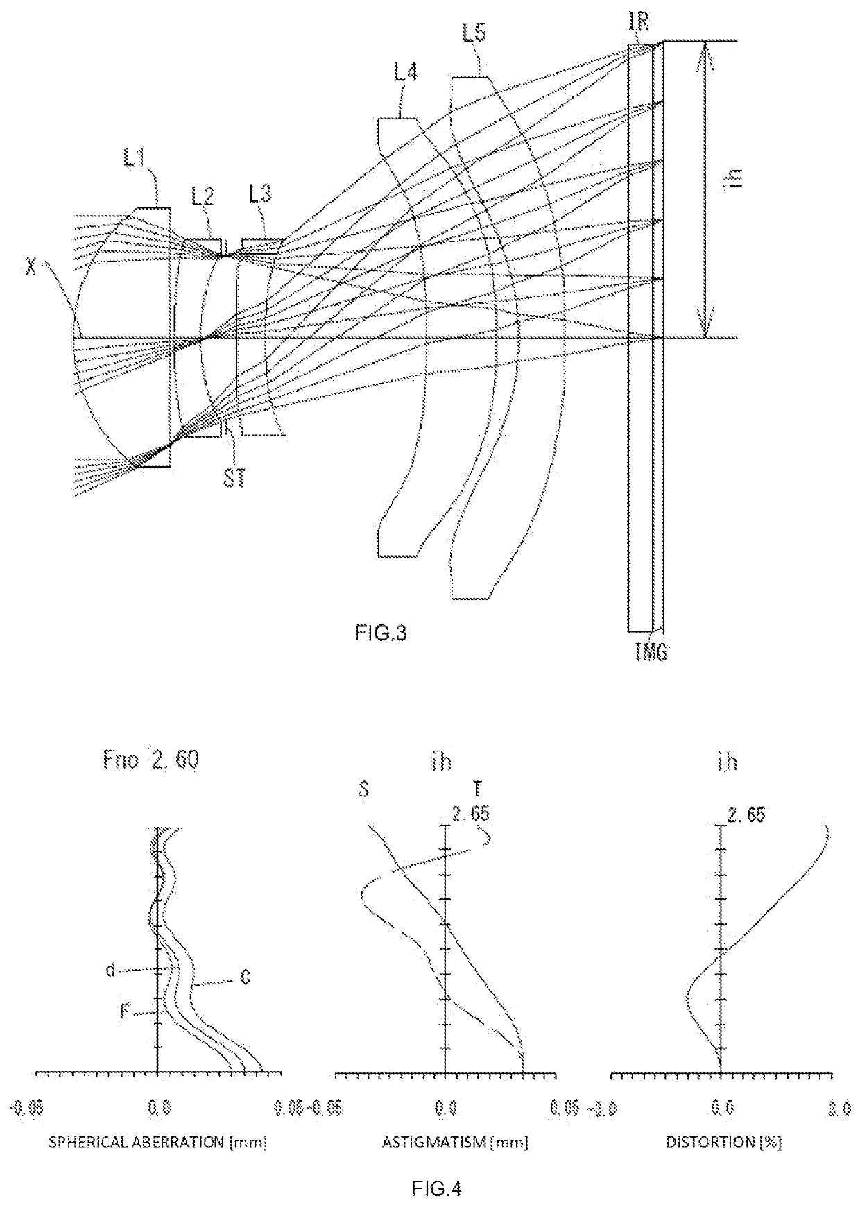
example 1
[0084]The basic lens data is shown below in Table 1.
TABLE 1Example 1Unit mmf = 5.80Fno = 2.60ω(°) = 24.0h = 2.65TTL = 5.26Surface DatairdNdνd(Object)InfinityInfinity1*1.41980.90001.54455.93 (νd1)2*25.46590.05313*7.04470.24001.66120.37 (νd2)4*2.25650.2275(Stop)Infinity−0.04406*3.36540.26001.53555.69 (νd3)7*2.11971.57018*−13.28800.57261.67119.24 (νd4)9*−5.62300.237210* −2.90440.37861.53555.69 (νd5)11* −13.41320.610212 Infinity0.21001.51764.2013 Infinity0.114214 InfinityImage PlaneConstituent Lens DataLensStart SurfaceFocal Length112.72723−5.12736−11.5474814.110510−7.020Aspheric Surface DataFirst SurfaceSecond SurfaceThird SurfaceFourth SurfaceSixth Surfacek−6.588456E−030.000000E+000.000000E+001.700524E+000.000000E+00A4−1.361478E−035.021949E−032.369351E−033.075795E−026.473803E−02A6 1.159582E−041.816469E−021.608441E−014.865807E−01−4.368833E−01 A8−5.169160E−032.413699E−02−2.992783E−01 −2.415816E+00 3.621573E+00A10 2.829951E−03−3.660923E−02 7.725731E−011.012343E+01−1.508344E+01 A12−2.6868...
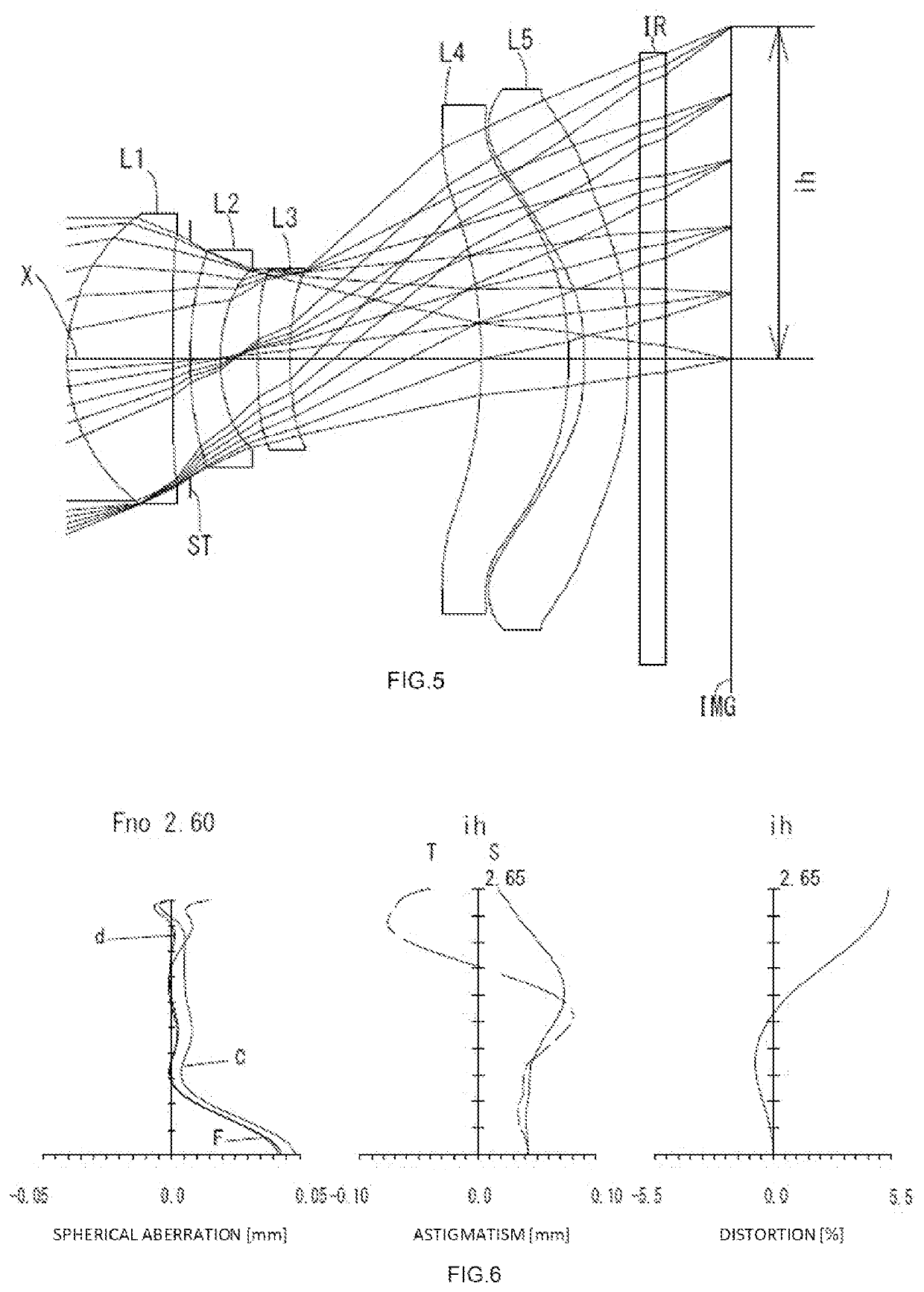
example 2
[0087]The basic lens data is shown below in Table 2.
TABLE 2Example 2Unit mmf = 5.86Fno = 2.60ω(°) = 24.0h = 2.65TTL = 5.23Surface DatairdNdνd(Object)InfinityInfinity1*1.45090.87361.54455.93 (νd1)2*−16.74740.03003*4.25080.24001.66120.37 (νd2)4*1.78860.2226(Stop)Infinity0.10216*−13.20750.26001.53555.69 (νd3)7*7.08411.44498*−6.99100.63111.67119.24 (νd4)9*−3.90210.195910* −2.91790.41491.53555.69 (νd5)11* Infinity0.575012 Infinity0.21001.51764.2013 Infinity0.100214 InfinityImage PlaneConstituent Lens DataLensStart SurfaceFocal Length112.495234.86236−8.5834812.169510−5.456Aspheric Surface DataFirst SurfaceSecond SurfaceThird SurfaceFourth SurfaceSixth Surfacek 1.653765E−010.000000E+000.000000E+00−1.936409E+000.000000E+00A4−5.825023E−032.863207E−02−7.328383E−02 −3.031466E−021.871475E−01A6−2.908529E−031.628884E−031.561475E−01 4.521889E−01−3.589476E−01 A8−6.649254E−032.558630E−02−1.942164E−01 −1.907027E+003.109420E+00A10 1.835901E−03−1.609026E−02 5.553624E−01 7.875217E+00−1.317657E+01 A12−1....
example 3
[0090]The basic lens data is shown below in Table 3.
TABLE 3Example 3Unit mmf = 6.10Fno = 2.60ω(°) = 22.7h = 2.65TTL = 5.26Surface DatairdNdνd(Object)InfinityInfinity1*1.43100.85161.54455.93 (νd1)2*−31.92790.1364(Stop)Infinity0.00004*2.90960.24001.66120.37 (νd2)5*1.31220.30236*9.21270.26011.53555.69 (νd3)7*3.77021.53058*−3.89080.70291.67119.24 (νd4)9*−2.54370.126110* −2.27530.35001.53555.69 (νd5)11* −9.03510.085712 Infinity0.21001.51764.2013 Infinity0.534014 InfinityImage PlaneConstituent Lens DataLensStart SurfaceFocal Length112.53924−3.84736−12.135489.056510−5.791Aspheric Surface DataFirst SurfaceSecond SurfaceFourth SurfaceFifth SurfaceSixth Surfacek0.000000E+000.000000E+000.000000E+000.000000E+000.000000E+00A4−2.253422E−02 −1.364740E−02 −1.776087E−01 −2.255569E−01 2.035696E−01A67.273765E−022.866077E−018.730512E−011.675486E+00−6.552966E−01 A8−1.551822E−01 −6.344121E−01 −1.897703E+00 −5.611616E+00 6.328115E+00A101.850978E−017.813626E−012.531389E+001.515057E+01−2.502062E+01 A12−1.22...
PUM
 Abstract
Description
Claims
Application Information