Single-Action Emergency Thermal Valve

Pending Publication Date: 2021-06-17
AKTSIONERNOE OBSHCHESTVO INZHINIRINGOVAYA KOMPANIYA ASE +2
View PDF1 Cites 0 Cited by
  • Summary
  • Abstract
  • Description
  • Claims
  • Application Information

AI Technical Summary

Benefits of technology

[0010]The task of this invention is to develop a design of a single-action emergency thermal valve with high reliability and efficiency, which is achi

Problems solved by technology

This valve shall operate reliably in emergency conditions with the temperature increase above the permissible value, however, due to the use of a ball as the locking element, the flow of the medium through the valve is limited and not stable.
The disadvantage of this technical solution is low reliability of operation of this valve, since the fuse link is remote from the monitored zone and located in the middle part of the valve body.
The disadvantages of this solution are low flow of the coolant in the cooli

Method used


Image

  • Single-Action Emergency Thermal Valve

Examples


Example

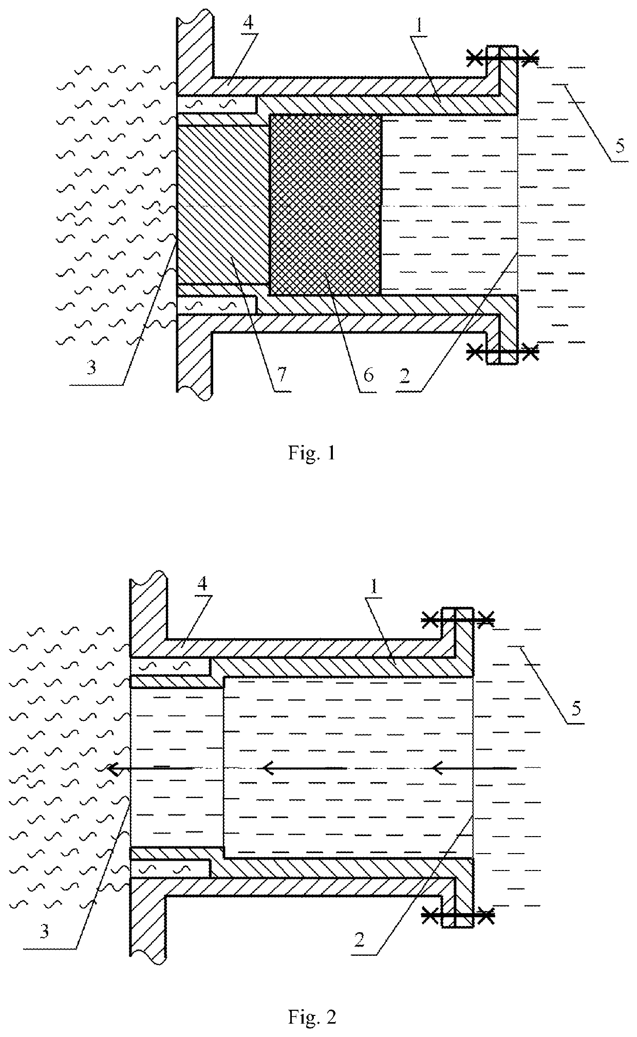
[0017]The claimed single-action emergency thermal valve in the preferred embodiment comprises a body 1 disposed and fixed in the room wall 4, with wherein an accident with a sharp increase in thermophysical parameters is possible (at your discretion: in technology they say “fixed to the wall”, since below you provide clarifications—the inlet / outlet of the valve, the areas it borders with). A through channel is provided in the body 1 with the inlet 2 and the outlet 3 designed to supply coolant from the container 5 to the area of high thermophysical parameters on the opposite side of the emergency thermal valve in the event of an emergency situation, i.e., exceeding of the design value of the medium temperature near the outlet 3. Inside the through channel, there is a fuse link that consists of the first part 6 contacting with the coolant and the second part 7 of the fuse link that is in contact with the medium with high thermophysical parameters; these parts completely overlap the se...


PUM


Abstract

The single-action emergency thermal valve comprises a body with a through channel for coolant supply through its inlet in the direction of its outlet, and a fuse link in the through channel of the body; the fuse link consists of at least two parts that completely overlap the section of the through channel, are made of materials with different melting points, and are located in the through channel in series with the increase of the melting temperature of each successive part in the direction from the through channel inlet to its outlet, wherein the body can have transverse ribs and/or transverse ridges at the location of the fuse link.

Description

CROSS-REFERENCE TO RELATED APPLICATIONS[0001]This application is a US 371 Application from PCT / RU2017 / 000776 filed Oct. 24, 2017, which claims priority to Russia Application 2017131093 filed Sep. 4, 2017, the technical disclosures of which are hereby incorporated herein by reference.FIELD OF THE INVENTION[0002]The invention relates to mechanical engineering, namely to emergency single-action thermal valves with a breakable insert, and can be used in metallurgy, oil, gas and nuclear industry, in particular at nuclear power plants, and in other fields of technology, in cases of need for supplying coolant to a volume with high thermophysical parameters in emergency situations.BACKGROUND OF THE INVENTION[0003]A thermal valve is known that comprises a locking device and a fuse link, which, if necessary, operates in a predetermined temperature range (RF patent 2149303, priority 23 Nov. 1991, IPC: F16K 17 / 40).[0004]This valve shall operate reliably in emergency conditions with the temperat...

Claims


Application Information

Patent Timeline
IPC IPC(8): F16K17/40
CPCF16K17/40F16K17/00F16K17/383
Inventor ZHURAVLEV, NIKOLAY YUR`EVICHSHMAL, IGOR IVANOVICH
Owner AKTSIONERNOE OBSHCHESTVO INZHINIRINGOVAYA KOMPANIYA ASE
Why Eureka
Try Eureka