Air refrigerant type cooling apparatus and air refrigerant cooling/heating system using refrigerant type cooling apparatus

a cooling apparatus and air refrigerant technology, applied in the direction of domestic cooling apparatus, piston pumps, lighting and heating apparatus, etc., can solve the problem of insufficient cooling of the motor as a whole in the conventional motor cooling method, and achieve the effect of high reliability, simplified configuration and high reliability

Active Publication Date: 2012-03-27
MITSUBISHI HEAVY IND LTD
View PDF9 Cites 0 Cited by
  • Summary
  • Abstract
  • Description
  • Claims
  • Application Information

AI Technical Summary

Benefits of technology

[0012]An object of the present invention is to provide an air refrigerant type cooling apparatus provided with a motor internal air cooling mechanism with high reliability and efficiency. Another object of the present invention is to provide an air refrigerant cooling / heating system with a simplified configuration using the air refrigerant type cooling apparatus.
[0023]With the above described configuration elements and the operation principle according to the present invention, it is possible to provide the highly reliable air refrigerant type cooling apparatus having the effective motor internal air cooling mechanism. It is also possible to provide the highly reliable air refrigerant cooling / heating system with a simplified configuration using the air refrigerant type cooling apparatus described above.

Problems solved by technology

If the ratio of the length in the stator coil end portion is increased, a heating value from the stator coil end portion is increased at the time of driving the motor, so that it is insufficient in the conventional motor cooling method to cool down the motor as a whole.

Method used


Image

  • Air refrigerant type cooling apparatus and air refrigerant cooling/heating system using refrigerant type cooling apparatus
  • Air refrigerant type cooling apparatus and air refrigerant cooling/heating system using refrigerant type cooling apparatus
  • Air refrigerant type cooling apparatus and air refrigerant cooling/heating system using refrigerant type cooling apparatus

Examples


first embodiment

(First Embodiment)

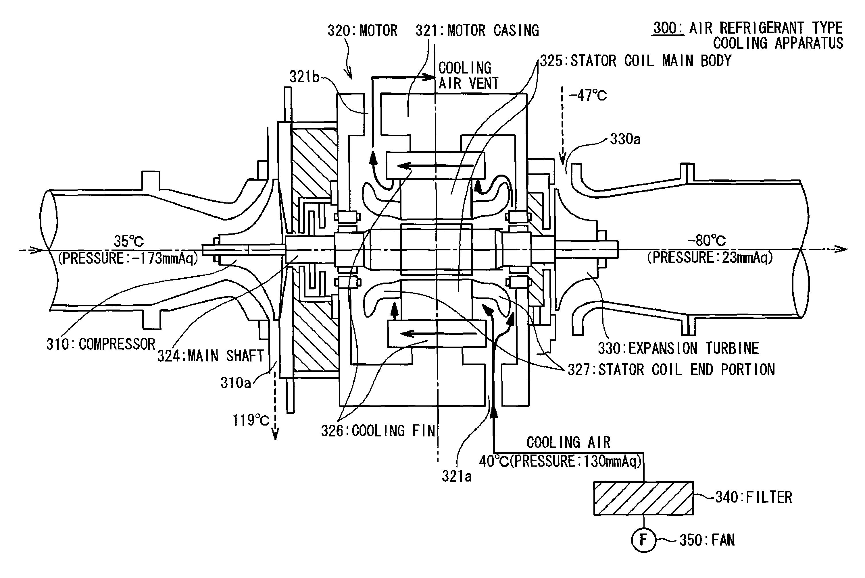
[0035]FIG. 3 shows a cross section of a schematic configuration of an air refrigerant type cooling apparatus 300 according to the first embodiment of the present invention. The air refrigerant type cooling apparatus 300 in the present embodiment includes a motor 320, a compressor 310, and an expansion turbine 330. The compressor 310 is connected to one end of the motor 320 in the shaft direction thereof. The expansion turbine 330 is also connected to the other end of the motor 320 in the shaft direction thereof in the opposite side of the compressor 310. The motor 320 is centrally positioned between the compressor 310 and the expansion turbine 330, and includes a main shaft 324 being a rotational driving portion to be inserted into a motor casing 321, a stator coil main body 325 for driving the main shaft 324, and stator coil end portions 327 which are symmetrically positioned in the shaft direction across the stator coil main body 325.

[0036]Explained next will be ...

second embodiment

(Second Embodiment)

[0045]FIG. 4 shows a cross section of a schematic configuration of an air refrigerant type cooling apparatus 400 according to a second embodiment of the present invention. A basic configuration of the air refrigerant type cooling apparatus 400 according to the present embodiment is similar to that of the air refrigerant type cooling apparatus 300 according to the first embodiment. It is also aimed to enhance efficiency in the device as whole by high speed rotation of a motor 420 being a configuration requirement in the same manner with the first embodiment, in which high reliability is required at the time of an actual operation. In the present embodiment, a guide plate 460 is further provided in a motor casing 421 to control cooling air introduced from a cooling air intake port 421a so as to flow into a stator coil end portion 427.

[0046]The air refrigerant type cooling apparatus 400 according to the present embodiment includes a motor 420, a compressor 410, and a...

third embodiment

(Third Embodiment)

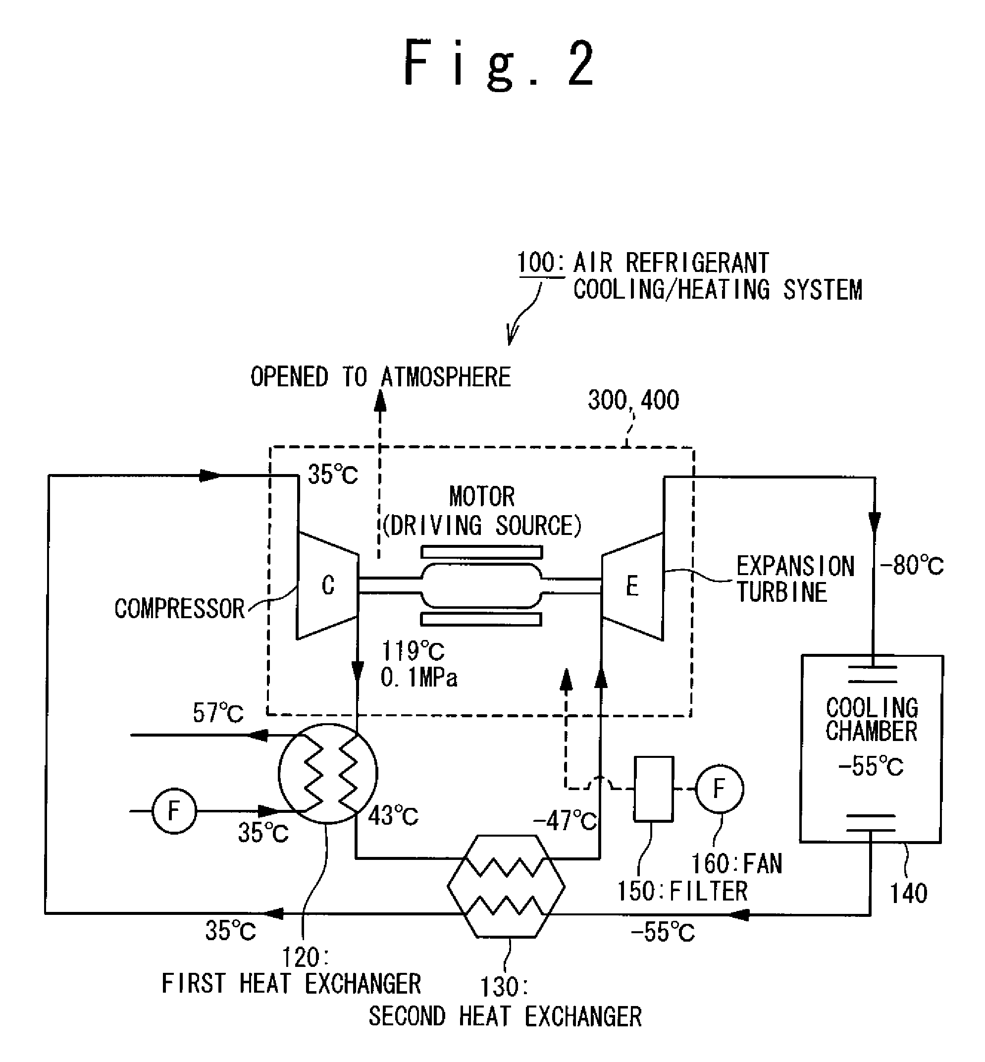
[0050]FIG. 2 shows a schematic diagram of an air refrigerant cooling / heating system 100 according to a third embodiment.

[0051]The air refrigerant cooling / heating system 100 according to the present embodiment includes the air refrigerant type cooling apparatuses 300 and 400 according to the first or second embodiment, the first heat exchanger 120, the second heat exchanger 130, the cooling chamber 140, a filter 150, and a fan 160.

[0052]A refrigerant used in the present embodiment is air, so that anxiety about environmental destruction caused by the ozone refrigerant which has been conventionally used is removed.

[0053]In the present embodiment, the outlet of the compressor in the air refrigerant type cooling apparatuses 300 and 400 is connected to an inlet of the first heat exchanger 120 by a pipe. An outlet of the first heat exchanger 120 is connected to an inlet of the second heat exchanger 130 by the pipe. The outlet of the second heat exchanger 130 is connected ...


PUM


Abstract

The purpose present invention is to provide an air refrigerant type cooling apparatus provided with an internal air cooling mechanism with high reliability and efficiency. Another object of the present invention is to provide an air refrigerant cooling / heating system with a simplified configuration using the air refrigerant type cooling apparatus. To accomplish the purpose, a heat radiating means is provided in a motor of an air refrigerant type cooling apparatus having a compressor, the motor and an expansion turbine in the present invention. Also, a pressure difference is positively generated between the inside and outside of the motor. By these means, when the motor is driven, the heat from the stator main body is exhausted to the outside of the motor through the heat radiating means and the heat from the coil end portions is exhausted through the cooling air exhausted from the inside to the outside of the motor. Further, a guide plate is located adjacent to the cooling air inlet in the motor, so that the intake cooling air is efficiently guided to the stator coil end portions. By this means, the heat generated from the coil end portions is efficiently exhausted from the inside to the outside of the motor. According to these configurations, an air refrigerant cooling apparatus can be realized. Moreover, by installing the air refrigerant cooling apparatus to a cooling / heating system, an air refrigerant cooling / heating system having simple configuration and very high reliability can be provided.

Description

CROSS-REFERENCE TO RELATED APPLICATIONS[0001]The present Application is based on International Application No. PCT / JP 2005 / 013714, filed on Jul. 27, 2005, which in turn corresponds to Japanese Application No. 2004-224940, filed on Jul. 30, 2004, and priority is hereby claimed under 35 USC §119 based on these applications. Each of these applications are hereby incorporated by reference in their entirety into the present application.TECHNICAL FIELD[0002]The present invention relates to an air refrigerant type cooling apparatus including an air cooling mechanism in a motor, and an air refrigerant type cooling / heating system which uses the air refrigerant type cooling apparatus including the air cooling mechanism in the motor.BACKGROUND ART[0003]An air refrigerant cooling / heating system is composed of an air refrigerant type cooling apparatus, a heat exchanger, and a cooling chamber, and an object thereof is to sustain products which are stored in the cooling chamber and required to be ...

Claims


Application Information

Patent Timeline
Patent Type & Authority Patents(United States)
IPC IPC(8): F25D9/00
CPCF04D25/04F04D25/082H02K9/04F25B9/004F04D29/584F04D25/06F04D29/5806
Inventor KIKUCHI, SHIGEMITSUOKUDA, SEIICHI
Owner MITSUBISHI HEAVY IND LTD
Why Eureka
Try Eureka