Stabilizer control system and method

a control system and stabilizer technology, applied in the field of stabilizers, can solve the problems that the existing stabilizer algorithm cannot adapt to the shooting device and cannot bring a good control effect to the stabilizer, and achieve the effect of high reliability and efficiency, and different variances of the detection modul

Active Publication Date: 2020-05-26
GUILIN FEIYU TECH CORP LTD
View PDF8 Cites 0 Cited by
  • Summary
  • Abstract
  • Description
  • Claims
  • Application Information

AI Technical Summary

Benefits of technology

[0021]Embodiments of the present invention have the following beneficial effects:
[0023]The stabilizer control method according to the present disclosure is based on the stabilizer control system, which has high reliability and efficiency. The stabilizer control method is implemented by generating a deviation value and enabling the controlling module to issue a command to adjust motion states of the motor according to the deviation value. Through the cascade PID control, the controlling module can adaptively select PID characteristic values according to the deviation value, thereby satisfying the stability requirement of the target object mounted on the stabilizer. By setting a feedback module, a closed loop system is formed by the controlling module, the driving module, the motor and the feedback module, thereby obtaining adaptive matching PID characteristic values. Since vibration state of the motor reflects vibration state of the target object, PID range is constantly adjusted according to the vibration state of the motor to obtain the adaptive matching PID characteristic values. In conclusion, when target objects with different weights are placed on the stabilizer, the variances of the detecting module are different due to different moments of inertia of the target objects, and the deviation values obtained by the controlling module are also different. The PID characteristic values obtained by the controlling module through the cascade PID control are also different, so that the controlling module can issue an adjustment signal to adjust the motion state of the motor. Therefore, the PID characteristic values are adjusted adaptively to realize that the stabilizer can adapt to different target objects.

Problems solved by technology

At present, the existing stabilizer algorithm can only adapt to shooting device of which weight and size is within preset ranges.
When weight and size of a shooting device is out of the preset ranges, it will not bring a good control effect on the stabilizer.

Method used


Image

  • Stabilizer control system and method
  • Stabilizer control system and method

Examples


Embodiment Construction

[0027]The technical solutions of the embodiments according to the present invention are clearly and fully described as below with reference to the accompanying drawings in the embodiments of the present invention. Apparently, the embodiments to be described are merely a part rather than all of the embodiments of the present invention. All other embodiments obtained by persons with ordinary skills in the art based on the embodiments of the present invention without creative efforts shall fall within the protection scope of the present invention.

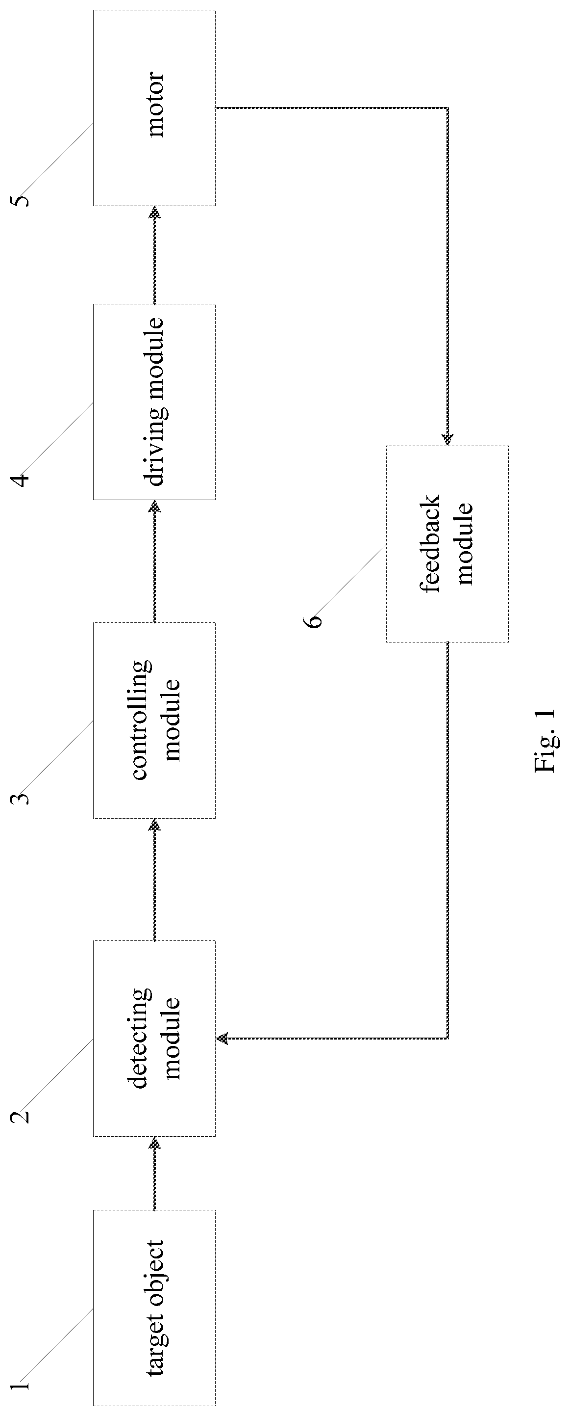
[0028]With reference to FIG. 1, a stabilizer control system according to the present embodiment comprises a detecting module 2, a controlling module 3, a driving module 4, a feedback module 6 and a motor 5;

[0029]the detecting module 2 detects posture information of a stabilizer, and sends the posture information to the controlling module 3;

[0030]a first input end of the controlling module 3 is connected with the detecting module 2; the control...


PUM


Abstract

The present invention provides a stabilizer control system and method, wherein the system comprises a detecting module, a controlling module, a driving module, a feedback module and a motor; the detecting module detects posture information of a stabilizer, and sends the posture information to the controlling module; the controlling module receives the posture information of the stabilizer and issues a command to the driving module according to a preset control strategy; an input end of the driving module is connected with an output end of the controlling module, the output end of the driving module is electrically connected with the motor; the driving module receives the command from the controlling module and adjusts a rotating speed of the motor according to the command; the feedback module detects the rotating speed of the motor and sends rotating speed data of the motor to the controlling module.

Description

CROSS-REFERENCE TO PRIOR APPLICATION[0001]This application claims the benefit of Chinese Patent Application No. 201810399334.9 filed on Apr. 28, 2018, the contents of which are incorporated herein by reference.FIELD OF THE INVENTION[0002]The present invention relates to stabilizer field, more particularly to a stabilizer control system and method.BACKGROUND OF THE INVENTION[0003]The stabilizer is used to fix the target object, adjust the attitude of the target object (for example, with regards to directional motion, rolling motion and pitching motion) and stabilize the target object in a determined posture, so as to enable the target object to achieve stable, smooth, and multi-angle shooting. So far, the target objects are mobile phones, video cameras and cameras.[0004]At present, the existing stabilizer algorithm can only adapt to shooting device of which weight and size is within preset ranges. When weight and size of a shooting device is out of the preset ranges, it will not brin...

Claims


Application Information

Patent Timeline
Patent Type & Authority Patents(United States)
IPC IPC(8): G01C21/18G03B17/56G01C21/20
CPCG03B17/561G01C21/20G01C21/18G03B2217/002G05B11/42H02P21/00H02P2205/07
Inventor WEI, CHENGYUN
Owner GUILIN FEIYU TECH CORP LTD
Why Eureka
Try Eureka