Ventilator-equipped engine

a technology of ventilators and engines, applied in the direction of combustion engines, crankcase ventillation, machines/engines, etc., can solve the problems of deteriorating ventilation efficiency inside the engine, and achieve the effect of enhancing the ventilation effect, and reducing the passage for fresh air introduction

Active Publication Date: 2021-06-24
KUBOTA LTD
View PDF0 Cites 0 Cited by
  • Summary
  • Abstract
  • Description
  • Claims
  • Application Information

AI Technical Summary

Benefits of technology

[0011]According to the present invention, fresh air is introduced into the internal space of the cylinder head. This configuration can prevent the fresh air from flowing straight through only the inside of the head cover and being discharged to the gas outlet of the head cover. Thus, the intended ventilation effect achieved by introducing fresh air into the crankcase is enhanced.
[0012]Therefore, the ventilation effect is enhanced as compared with a configuration where fresh air is supplied to the head cover, and a risk that the fresh air introduction passage is closed is decreased as compared with a configuration in which fresh air is supplied into the crankcase. Accordingly, a ventilator that can enhance the ventilation effect while decreasing a possibility of closure due to freezing can be achieved.
[0013]As a result, it is possible to provide a ventilator-equipped engine which has been improved so as to enhance ventilation efficiency in the engine.

Problems solved by technology

This may deteriorate ventilation efficiency inside the engine (crankcase).

Method used


Image

  • Ventilator-equipped engine
  • Ventilator-equipped engine
  • Ventilator-equipped engine

Examples


Embodiment Construction

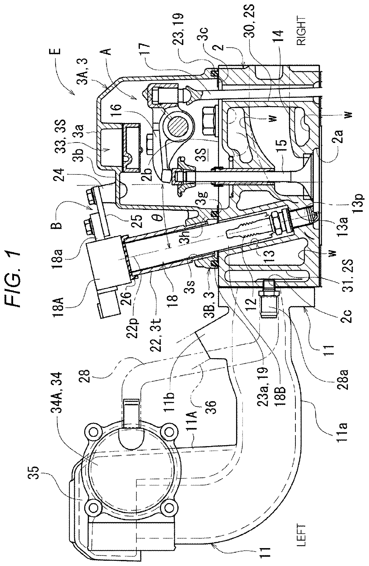
[0026]An embodiment of a ventilator-equipped engine according to the present invention will be described with reference to the drawings, taking an example in which the ventilator-equipped engine is an industrial spark ignition engine (gasoline engine, etc.) used for agricultural machinery, construction machinery, generators, working machines, and the like.

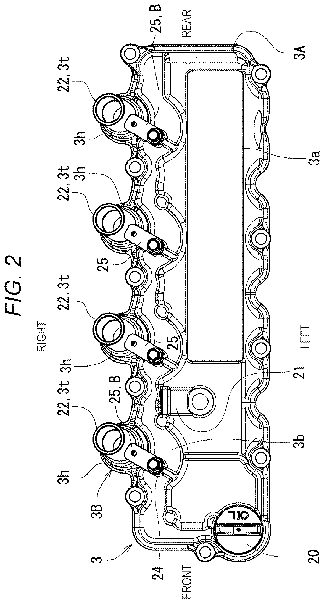
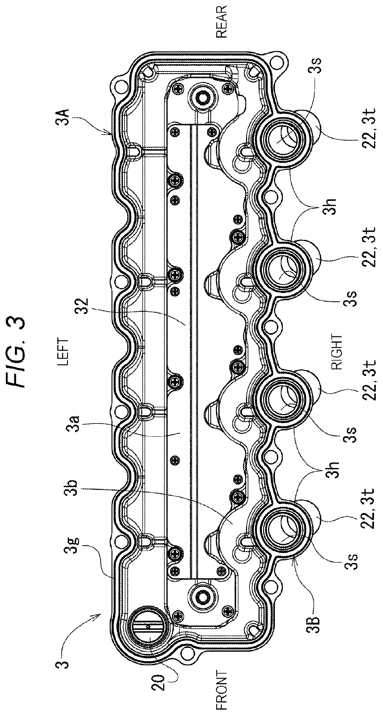
[0027]As shown in FIGS. 5 to 8, a spark ignition engine E (hereinafter, simply referred to as “engine”) includes a cylinder block 1, a cylinder head 2 mounted on the cylinder block, and a head cover 3 mounted on the cylinder head 2. The cylinder block 1 has a crankcase 1A below which an oil pan 4 is mounted, and a cylinder 1B which houses a piston (not shown).

[0028]The engine E is equipped with a transmission belt 5, an engine cooling fan 6, a water flange 7, and the like on the front part, and a flywheel housing 8 on the rear part.

[0029]The engine E is equipped with an exhaust manifold 9 and an exhaust cover 10 covering the exhaus...


PUM


Abstract

The ventilator-equipped engine is configured to: guide a blow-by gas generated in a crankcase to an intake passage through an inside of a cylinder head, an inside of a head cover, and a pressure regulating valve; and to directly introduce fresh air into an internal space of the cylinder head by providing a fresh air introduction passage that extends across the intake passage and the cylinder head.

Description

CROSS-REFERENCE TO RELATED APPLICATION[0001]This application claims priority under 35 U.S.C. § 119(b) to Japanese Patent Application No. 2019-230942 filed on Dec. 20, 2019, the disclosure of which is incorporated herein by reference in its entirety.BACKGROUND OF THE INVENTIONField of the Invention[0002]The present invention relates to a ventilator-equipped engine.Description of Related Art[0003]A blow-by gas recirculation device is configured to guide a blow-by gas generated in a crankcase to an intake passage through the inside of a cylinder head, the inside of a head cover, and a pressure regulating valve.[0004]In order to effectively prevent an increase in pressure in the engine and oil contamination due to a blow-by gas, some engines employ a configuration in which a fresh air introduction passage and a blow-by gas discharge passage are connected to the inside of the engine, and a blow-by gas is returned to an intake passage using these passages.[0005]Normally, in a ventilator-e...

Claims


Application Information

Patent Timeline
Patent Type & Authority Applications(United States)
IPC IPC(8): F01M13/02F01M13/04
CPCF01M13/022F01M2013/0083F01M13/04F01M2013/0038F01M2013/005F01M13/023F01M13/0416Y02T10/12F01M2013/0044F01M2013/0438
Inventor ISOSHIMA, HIROAKIKAWASAKI, TAKESHIYAMADA, YUICHIRO
Owner KUBOTA LTD
Why Eureka
Try Eureka