Manufacturing method for fuel cell

Active Publication Date: 2021-06-24
TOYOTA JIDOSHA KK
View PDF0 Cites 0 Cited by
  • Summary
  • Abstract
  • Description
  • Claims
  • Application Information

AI Technical Summary

Benefits of technology

The patent describes a configuration where multiple cell units can be placed without needing to accurately position each unit. This makes the manufacturing process faster because it doesn't require precise placement. The cell units can also be laminated without damaging the sealing portions when the shelf device is moved. Additionally, the configuration makes it easy to accurately position each cell unit, further shortening the manufacturing time.

Problems solved by technology

This requires time to manufacture a laminated body of the cells.
However, in such a process, a sealing portion provided in each of the cells such that the sealing portion projects from a surface of the each of the cells might be distorted and damaged.

Method used


Image

  • Manufacturing method for fuel cell
  • Manufacturing method for fuel cell
  • Manufacturing method for fuel cell

Examples


embodiment 1

B1. Another Embodiment 1

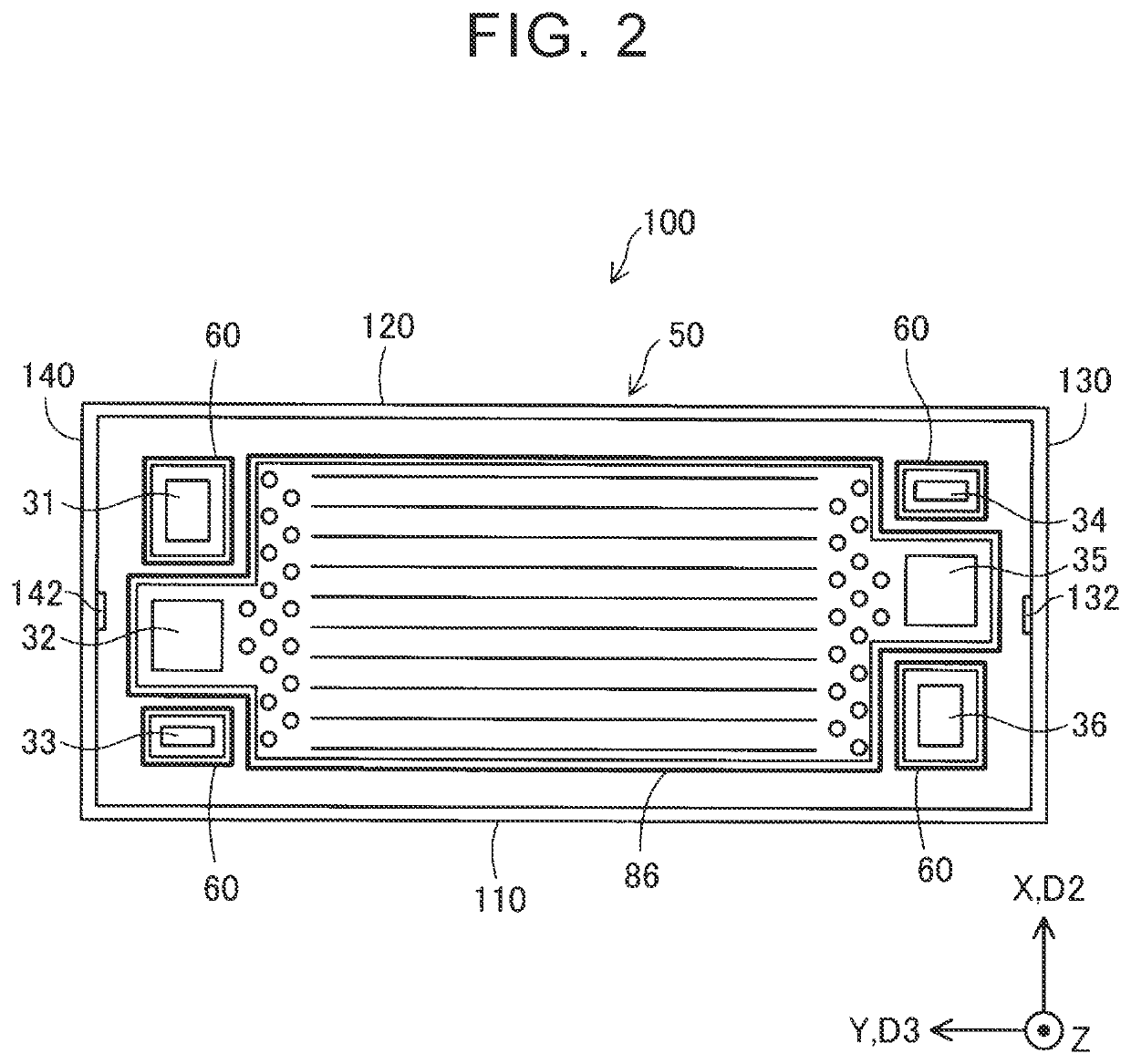
[0063](1) In the above embodiment, the power generation cell unit 100 has a generally rectangular outer shape (see FIG. 2). However, the cell unit may have other shapes such as a generally parallelogram, a generally trapezoid, a generally diamond, and a shape similar to a quadrangular shape that does not have sides parallel to each other. Further, the cell unit may have a polygonal shape other than a quadrangle, a circle, or a shape having a part projecting inwardly. Note that it is preferable that the cell unit have an outer shape the outline shape of which is a generally quadrangle.

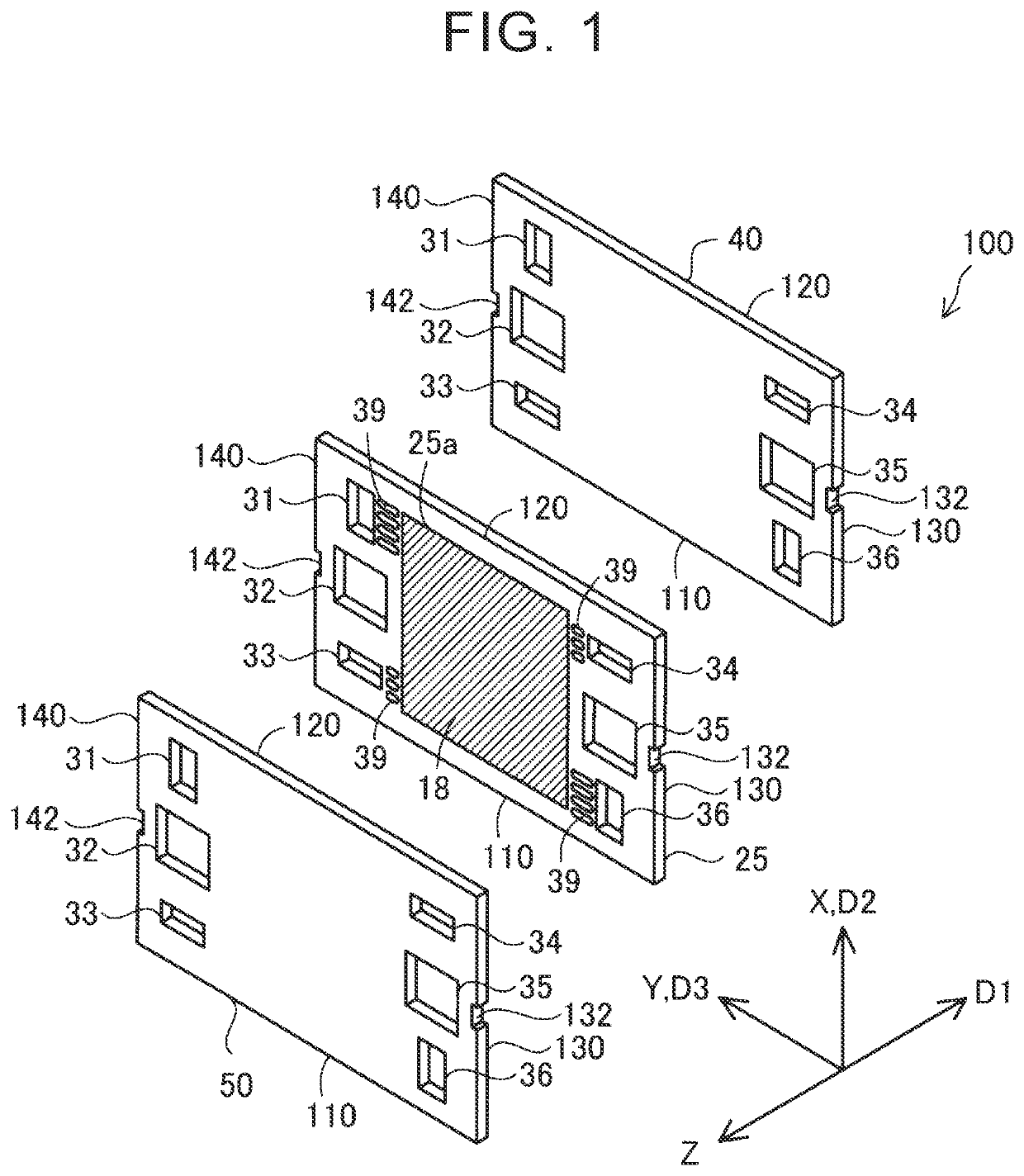
[0064](2) In the above embodiment, the power generation cell unit 100 includes the MEGA 18, the separators 40, 50, and the first resin frame 25 (see FIG. 1). However, the cell unit may be a unit including two or more MEGAS. In such a cell unit, one separator may be disposed between the MEGAS adjacent to each other, or two or more separators may be disposed between the MEGAS adjac...


PUM


Abstract

A shelf device including a plurality of shelves is prepared. A quadrangular plate-shaped cell unit can be placed on each of the selves. A plurality of cell units is placed such that the cell units are disposed on respective shelves. The cell unit is disposed on the shelf such that the second part is placed between the recessed portions. The cell units are disposed on the shelves such that corresponding recessed portions of the cell units overlap each other. A pair of jigs extending in a first direction is placed such that the jigs are disposed inside the recessed portions of the cell units. The shelf device is caused to retreat from the cell units and the jigs, and relative positions of the cell units are changed along the jigs so that the cell units make contact with each other.

Description

CROSS-REFERENCE TO RELATED APPLICATION[0001]This application claims priority to Japanese Patent Application No. 2019-229374 filed on Dec. 19, 2019, incorporated herein by reference in its entirety.BACKGROUND1. Technical Field[0002]This disclosure relates to a manufacturing method for a fuel cell.2. Description of Related Art[0003]In the related art, there is a technology to laminate cells by use of a lamination jig (Japanese Unexamined Patent Application Publication No. 2010-212139 (JP 2010-212139 A)). In the technology of JP 2010-212139 A, the lamination jig includes a base plate and a guide bar extending in the normal direction of the base plate. In the technology of JP 2010-212139 A, by means of a mounting unit, a plurality of cells is mounted along the guide bar from an open end of the guide bar such that the normal direction of the base plate and the normal direction of the cells are set along the same direction, and thus, the cells mounted on the lamination jig are aligned in ...

Claims


Application Information

Patent Timeline
IPC IPC(8): H01M8/2404
CPCH01M8/2404Y02P70/50H01M8/242H01M2008/1095Y02E60/50
Inventor TOYODA, KEIJISATO, KATSUMI
Owner TOYOTA JIDOSHA KK
Why Eureka
Try Eureka