Saw blade clamping device

Active Publication Date: 2014-12-11
BOSCH POWER TOOLS CHINA +1
View PDF10 Cites 1 Cited by
  • Summary
  • Abstract
  • Description
  • Claims
  • Application Information

AI Technical Summary

Benefits of technology

[0008]In the saw blade clamping device according to the invention, the operating member is provided with the driving surface, by means of which an operator can perform operation easily. Thus, the saw blade clamping device of the invention is easy to be operated.
[0009]In this way, the invention provides an advantageous option to users.

Problems solved by technology

A defect in such a clamping device 100′ is that it is difficult for an operator to insert a corresponding saw blade to an accurate position, which may result in that the first driving element 50′ and the second driving element 60′ fail to drive the first clamping plate 30′ and the second clamping plate 40′ into correct clamping condition.

Method used


Image

  • Saw blade clamping device
  • Saw blade clamping device
  • Saw blade clamping device

Examples


Embodiment Construction

[0021]Now the principle of a saw blade clamping device according to the invention will be described with reference to the drawings.

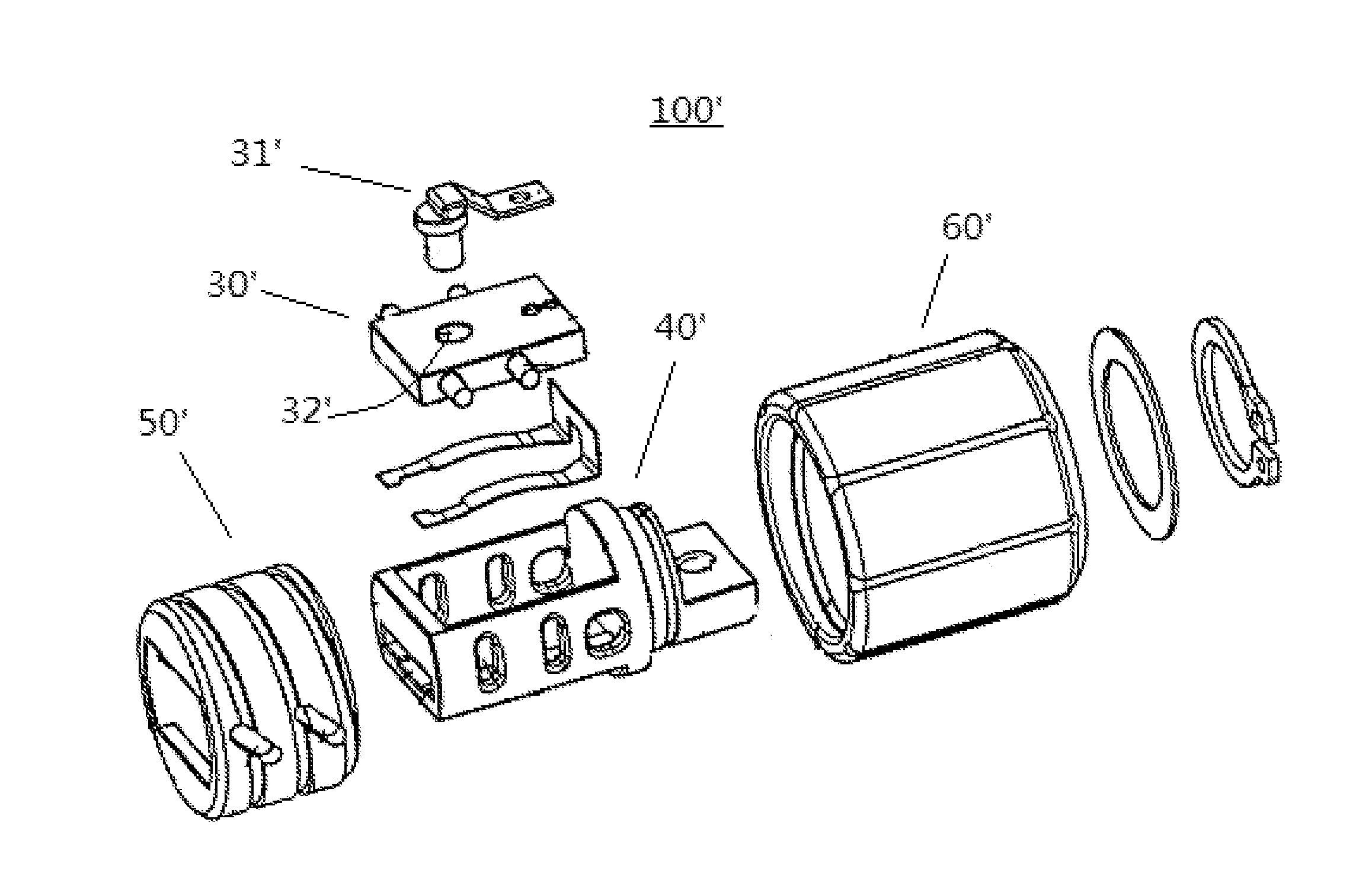
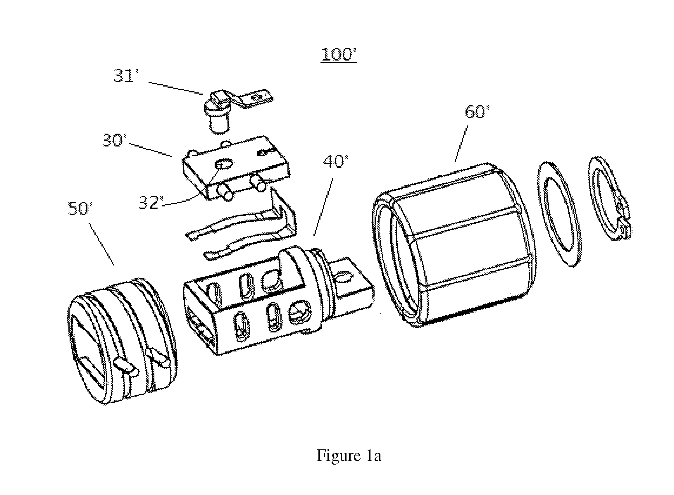
[0022]The invention relates to a saw blade clamping device 100 which is mainly used with linearly reciprocating type sawing machines, such as jigsaws or reciprocating saws, for loading saw blades therein, so that cutting operations can be performed by using the linearly reciprocating type sawing machines.

[0023]As shown in FIG. 2, a jigsaw blade 10 and a reciprocating saw blade 20 have shanks of different shapes, and the saw blade clamping device 100 of the invention is able to clamp the shank 11 of the jigsaw blade 10 as well as the shank 21 of the reciprocating saw blade 20.

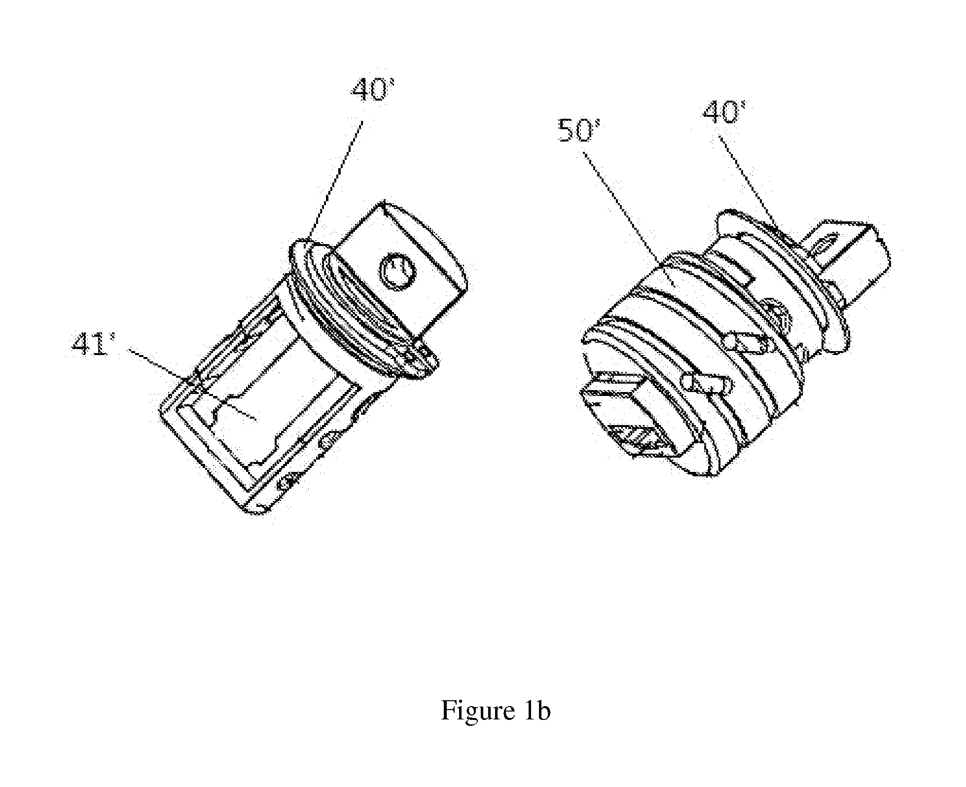
[0024]As shown in FIGS. 3a and 3b, the saw blade clamping device 100 of the invention comprises a clamping seat 30, an abutting element comprising a U-shaped member 40 and a fixing pin 50, an elastic member 60, a holding member 70, and an operating member 80.

[0025]The clamping seat 3...


PUM

PropertyMeasurementUnit
lengthsaaaaaaaaaa
lengthaaaaaaaaaa
spring forceaaaaaaaaaa

Abstract

A saw blade clamping device for a linearly reciprocating type sawing machine is able to clamp at least two types of saw blades, comprising a clamping seat having a connecting portion and a loading portion with a loading slot; an operating member comprising an operating portion and assembling and loading ends formed on opposite ends of the operating portion respectively, the operating portion being assembled around the loading portion by the help of the assembling end, and the loading end being provided with a loading port; and an abutting element disposed between the operating member and the clamping seat and having an abutting end which can extend into the loading slot, wherein the operating member is able to be rotated with respect to the loading portion, an inner wall of the operating member is provided with a driving surface formed in the form of a curved surface, the abutting element is provided with a driving end which abuts against the driving surface, and the abutting end of the abutting element is driven by the driving surface during the rotation of the operating member to move into the loading slot.

Description

TECHNICAL FIELD[0001]The invention relates to a saw blade clamping device for a hand-held machine tool, in particular to a saw blade clamping device which can be used in a hand-held linearly reciprocating type sawing machine and is able to clamp two types of saw blades.BACKGROUND ART[0002]FIGS. 1a and 1b show a saw blade clamping device 100′ used in a hand-held linearly reciprocating type sawing machine according to prior art. The saw blade clamping device is able to clamp either of a jigsaw blade 10 and a reciprocating saw blade 20 which have different shanks as shown in FIG. 2. The saw blade clamping device 100′ comprises a first clamping plate 30′, a second clamping plate 40′, a first driving element 50′, a second driving element 60′, and a fixing pin 31′ assembled to the first clamping plate 30′, wherein the second clamping plate 40′ is provided with a slot 41′ having a shape matching with that of the shank 11 of the jigsaw blade 10.[0003]The first driving element 50′ and the se...

Claims


Application Information

Patent Timeline
Patent Type & Authority Applications(United States)
IPC IPC(8): B23D51/10B23D49/16
CPCB23D49/16B23D51/10Y10T83/9481
Inventor WANG, YANCHAO
Owner BOSCH POWER TOOLS CHINA
Why Eureka
Try Eureka