Panel device including a panel and a support mechanism

a panel device and support mechanism technology, applied in the direction of machine supports, mechanical apparatus, television systems, etc., can solve the problems of preventing affecting the compactness of the work machine, so as to improve the usability of the panel device, prevent the rotation of the arm, and facilitate the viewing

Active Publication Date: 2019-06-18
FUJI MASCH MFG CO LTD
View PDF10 Cites 0 Cited by
  • Summary
  • Abstract
  • Description
  • Claims
  • Application Information

AI Technical Summary

Benefits of technology

[0013]Further, the support mechanism that supports the panel includes a first support axis fixed to the work machine, a second support axis fixed to the panel, a connecting arm that is swingably held by the first support axis and the second support axis and connects the first support axis and the second support axis, a guide rail formed on one of the work machine and the panel, an engaging member engaged with the guide rail that moves along the guide rail, and a regulating arm attachable to the engaging member and held on the other of the work machine and the panel so as to be oscillatable by one of the first support axis and the second support axis. Further, when the panel rotates, the rotation angle of the connecting arm with respect to the first support axis and the rotation angle of the connecting arm with respect to the second support axis are regulated by the regulating arm. That is, when the connecting arm oscillates, because the oscillation of the connecting arm and the rotation angle of the panel are regulated by the regulating arm, the display screen or the like of the panel is able to be maintained in a state facing a specified direction. Thus, according to the disclosed panel device, the display surface or the like of the panel is easy to view even when the panel is moved
[0014]Further, with the panel device having a support mechanism including a rotation prevention device, at least one of rotation of the connecting arm with respect to the first support axis and rotation of the connecting arm with respect to the second support axis is prevented. Thus, the panel is prevented from striking the work machine and so on.
[0015]Further, when the engaging member is moved to at least one of the ends of the guide rails, at least one of rotation of the connecting arm with respect to the first support axis and rotation of the connecting arm with respect to the second support axis is prevented. Thus, the engaging member is prevented from striking the ends of the guide rails.
[0016]Further, with the panel device having a support mechanism including an operating member provided on a side section of the panel when an operator moves the panel, it is possible to release the prevention of rotation of the arm by grasping the side section of the panel. This makes it easy for an operator to perform operation to release the prevention of rotation of the arm and operation for moving the panel at the same time, thereby improving usability of the panel device.
[0017]Further, with the panel device having the first support axis, the second support axis, the connecting arm, and the regulating arm provided on a rear surface of the panel, the first support axis, the second support axis, the connecting arm, and the regulating arm are provided on a rear surface of the panel. Thus, it is easy to make the external appearance of the front side of the panel device simple.
[0018]Further, with the work machine provided with a work machine cover, and the panel positioned in front of the work machine cover when the panel is rotated to the work machine side, when an operator performs maintenance or the like inside the work machine with the work machine cover open, the panel is an extreme nuisance, so the operator will move the panel. Here, there are cases in which work is performed while viewing the panel, so usability worsens if it is no longer possible to view the display screen of the panel due to the panel having been moved. Thus, a panel device for which it is easy to view the display screen of the panel even when the panel is moved is desirable. Thus, with the work machine according to claim 6, the effects of a panel device for which it is easy to view the display screen of the panel even when the panel is moved are sufficiently enabled.

Problems solved by technology

In recent years, work machines have become more compact, so securing arrangement space for a panel device is problematic.
Thus, there are cases in which panel devices are provided in front of work machine covers, or in front of other devices or the like, causing an obstruction to other work.
However, as the panel is moved, the direction of the surface of the panel, that is, the display surface or the input surface, changes, making it difficult for an operator to see the display surface or the like of the panel.
Specifically, for example, if an operator rotates a panel that is facing the operator 90 degrees around the support axis, the operator is then facing the side surface of the panel, making viewing the display surface of the panel difficult.

Method used


Image

  • Panel device including a panel and a support mechanism
  • Panel device including a panel and a support mechanism
  • Panel device including a panel and a support mechanism

Examples


Embodiment Construction

[0036]The following describes in detail referring to the figures an example embodiment of the present disclosure.

Configuration of Electronic Component Mounter

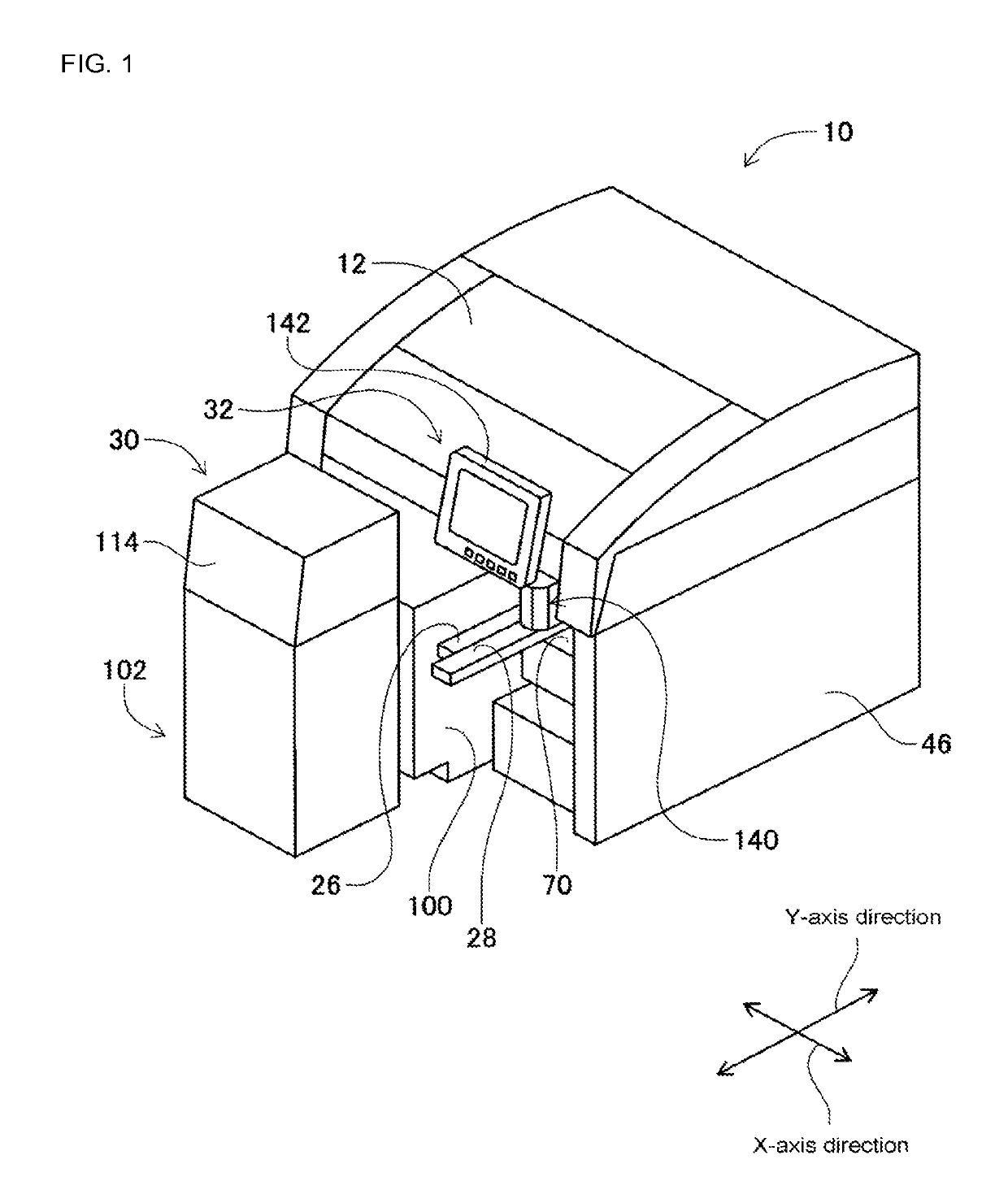
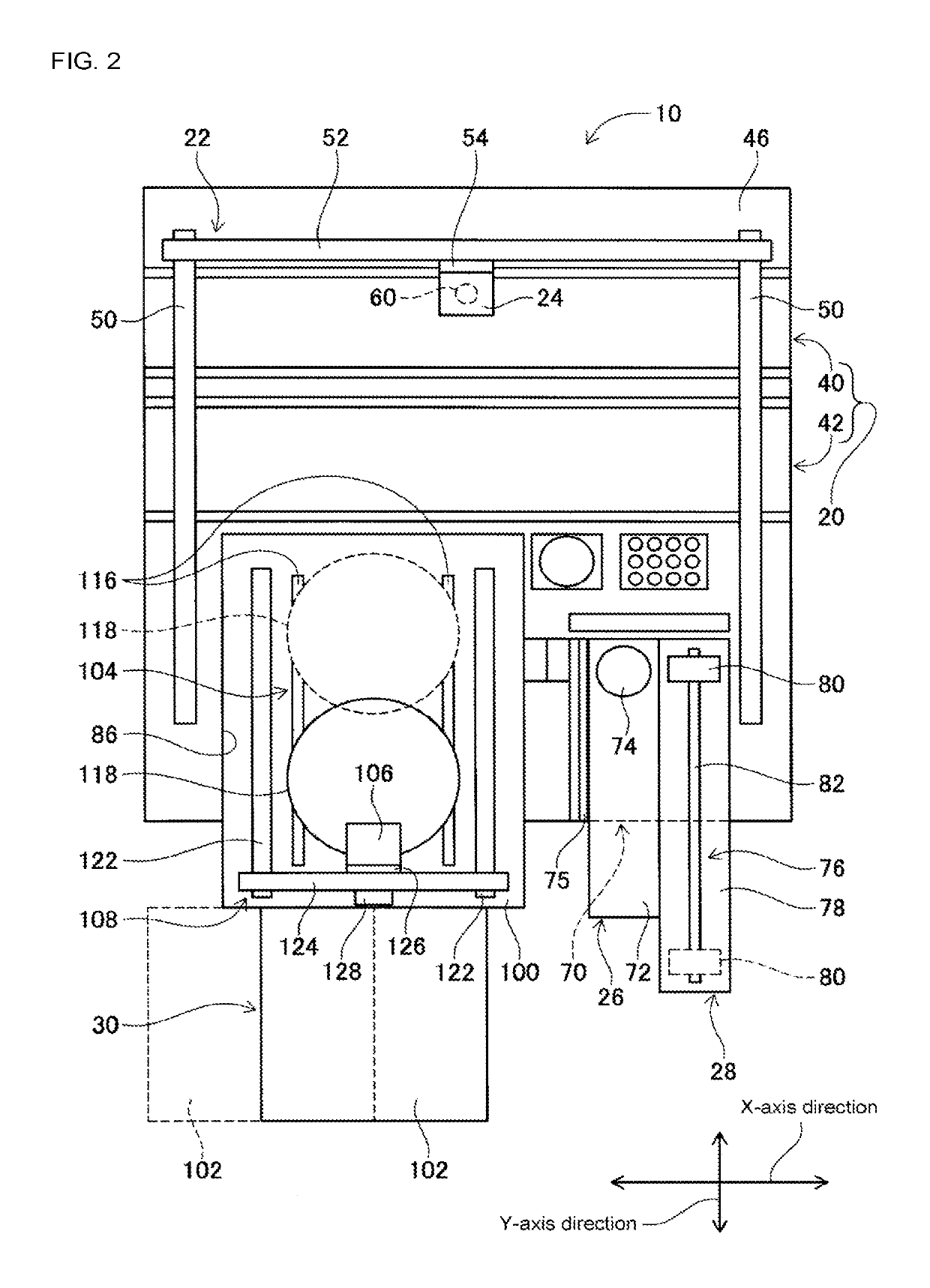
[0037]FIGS. 1 and 2 show electronic component mounter 10 of an embodiment of the present disclosure. FIG. 1 is a perspective view of electronic component mounter 10, and FIG. 2 is a plan view showing electronic component mounter 10 from which cover 12 and the like have been removed. Electronic component mounter 10 is a working machine that mounts electronic components on a circuit board. Electronic component mounter 10 is provided with conveyance device 20, mounting head moving device (hereinafter, referred to as a “moving device”) 22, mounting head 24, flux supply device 26, electronic component ejection device 28, die supply device 30, and panel device 32. Note that, in the following description, the width direction of electronic component mounter 10 is referred to as the X-axis direction and a horizontal direction orthogonal...


PUM


Abstract

A panel device including a panel for performing at least one of input and output of information related to operation of a work machine, a panel-side support axis fixed to the panel, a connecting arm that is swingably held by the two support axes, a guide rail formed on the work machine side, a bolt that moves along the guide rail, and a regulating arm attached to the bolt and held so as to be oscillatable by the panel-side support axis. When the connecting arm is oscillated, the oscillation of the connecting arm and the angle of the panel is regulated by the regulating arm.

Description

TECHNICAL FIELD[0001]The present application relates to a panel device for performing at least one of input and output of information related to operation of a work machine, and a work machine provided with the panel device.BACKGROUND ART[0002]Many work machines are provided with a panel device for performing at least one of input and output of information related to operation of the work machine. Among such panel devices are items with panels that are supported rotatably and items for which the position of the panel is changeable. With the panel devices disclosed in the patent literature below, the panel is rotatable around a support axis, or the panel is movable around a support axis.[0003]Patent Literature 1: JP-A-2009-170442[0004]Patent Literature 2: JP-A-2007-035744Summary[0005]In recent years, work machines have become more compact, so securing arrangement space for a panel device is problematic. Thus, there are cases in which panel devices are provided in front of work machin...

Claims


Application Information

Patent Timeline
Patent Type & Authority Patents(United States)
IPC IPC(8): H05K13/00F16M11/02H05K13/04H05K13/08F16M13/00F16M11/08F16M13/02H01L21/67H04N5/64
CPCH05K13/046F16M11/02F16M11/08F16M13/00F16M13/022H01L21/67144H05K13/0069H05K13/0888F16M2200/021H04N5/64F16M11/045F16M11/048F16M11/2014F16M13/02F16M2200/024
Inventor MURAI, MASAKIYAMASAKI, TOSHIHIKOSHIMIZU, TOSHINORI
Owner FUJI MASCH MFG CO LTD
Why Eureka
Try Eureka