Close-in Sensing Camera System

a camera system and sensor technology, applied in the field of exterior sensor systems, can solve problems such as affecting driving decisions and other autonomous operations, and achieve the effect of complete understanding of the environmen

Active Publication Date: 2021-07-01
WAYMO LLC
View PDF1 Cites 6 Cited by
  • Summary
  • Abstract
  • Description
  • Claims
  • Application Information

AI Technical Summary

Benefits of technology

[0003]The technology relates to an exterior sensor system for a vehicle configured to operate in a self-driving (autonomous) mode. Generally, sensors are used to detect objects in the environment around the vehicle. These can include lidar, radar, cameras, sonar and/or other sensors. Different sensors have various benefits, and sensor fusion from multiple sensors can be employed to obtain a more complete understanding of the environment so that the vehicle can make driving decisions. However, depending on the size...

Problems solved by technology

However, depending on the size, shape, etc. of the vehicle and objects in the environm...

Method used


Image

  • Close-in Sensing Camera System
  • Close-in Sensing Camera System
  • Close-in Sensing Camera System

Examples


example vehicle

SYSTEMS

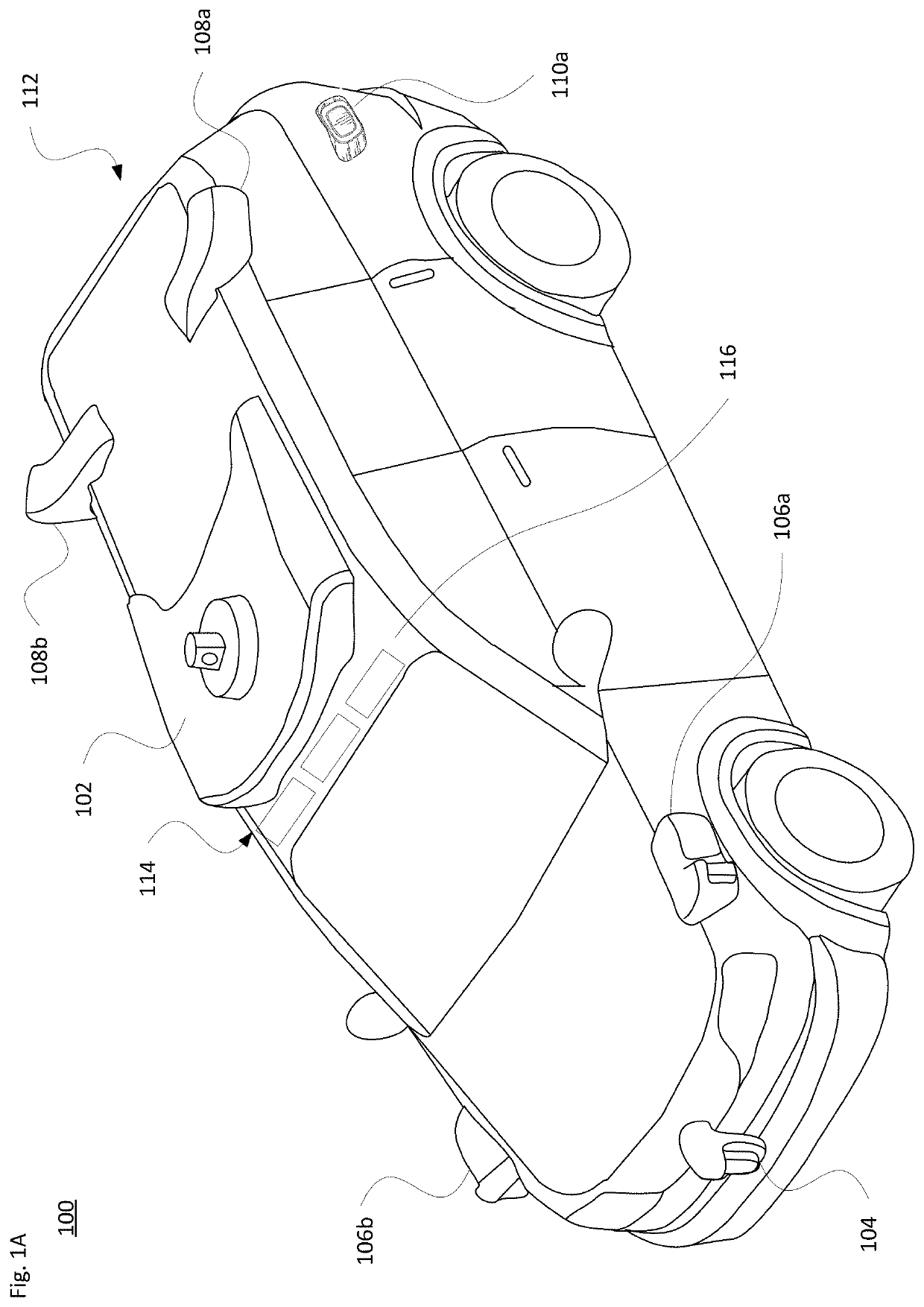
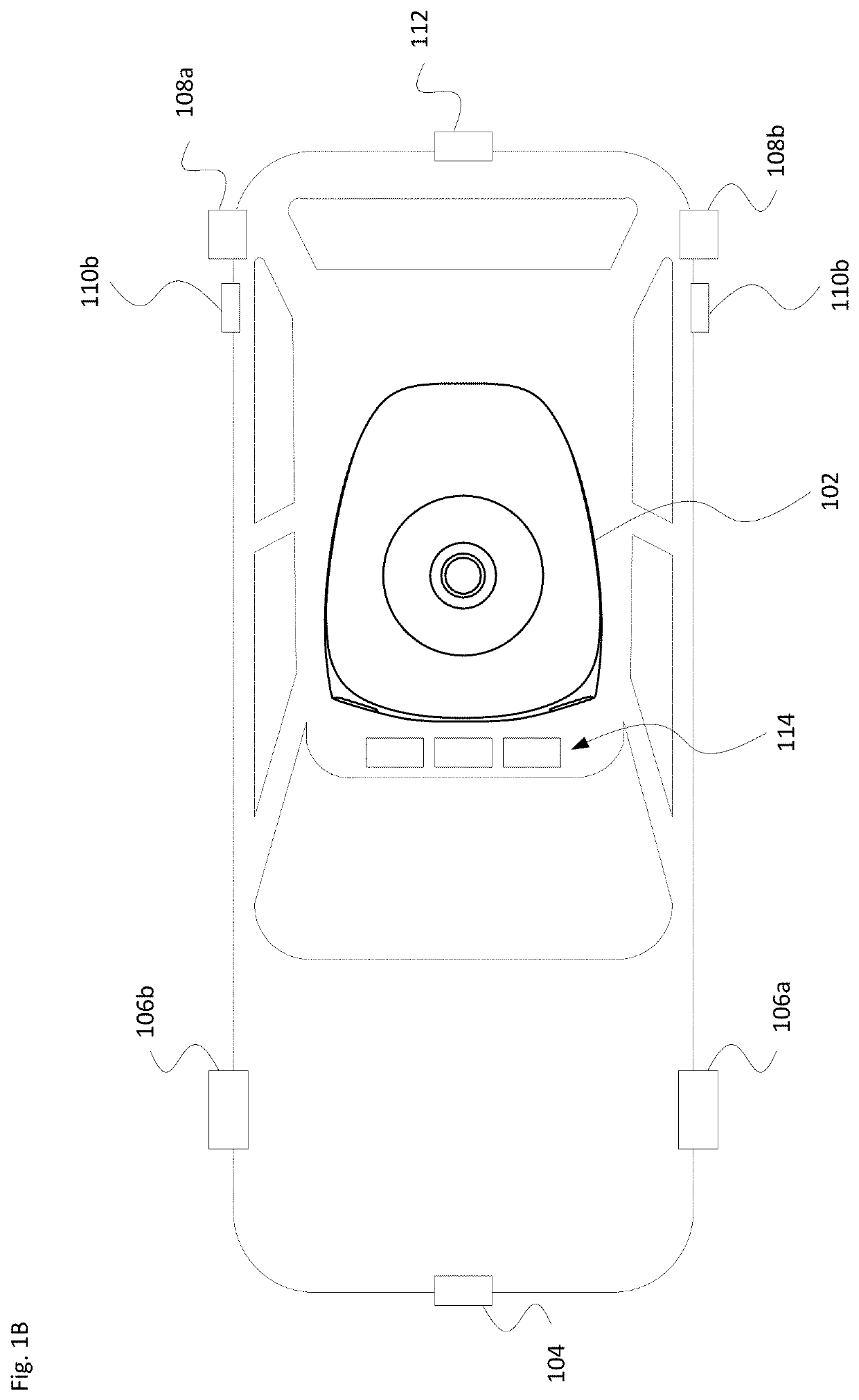
[0033]FIG. 1A illustrates a perspective view of a passenger vehicle 100, such as a minivan, sedan or sport utility vehicle. FIG. 1B illustrates a top-down view of the passenger vehicle 100. The passenger vehicle 100 may include various sensors for obtaining information about the vehicle's external environment. For instance, a rooftop housing 102 may include a lidar sensor as well as various cameras, radar units, infrared and / or acoustical sensors. Housing 104, located at the front end of vehicle 100, and housings 106a, 106b on the driver's and passenger's sides of the vehicle may each incorporate a lidar and / or other sensors. For example, housing 106a may be located in front of the driver's side door along a quarterpanel of the vehicle. As shown, the passenger vehicle 100 also includes housings 108a, 108b for radar units, lidar and / or cameras also located towards the rear roof portion of the vehicle. Other housings 110a, 110b may be located along the rear quarterpanels, for i...

example implementations

[0062]In view of the structures and configurations described above and illustrated in the figures, various implementations will now be described in accordance with aspects of the technology.

[0063]The environment around the vehicle can be viewed as having different quadrants or regions. One example 300 is illustrated in FIG. 3, which shows front, rear, right side and left side regions, as well as adjacent areas for the front right, front left, right rear and left rear areas around the vehicle. These regions are merely exemplary. The vehicle's perception system may cover some or all of the regions around the vehicle to provide as much information as possible about objects in the vehicle's external environment.

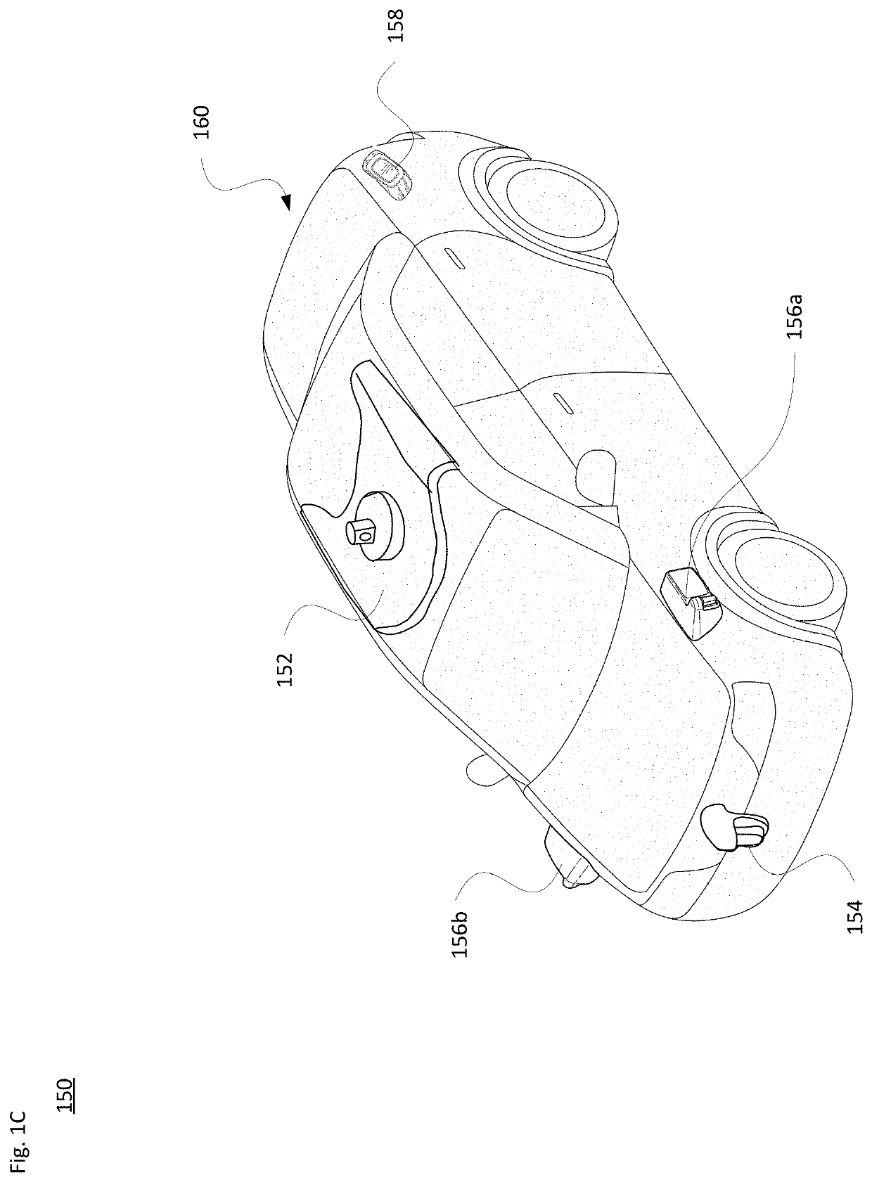
[0064]For instance, various sensors may be located at different places around the vehicle (see FIGS. 1A-C) to gather data from some or all of these regions. By way of example, the three sensors 116 of FIG. 1 may primarily receive data from the front, front left and front right re...


PUM


Abstract

The technology relates to an exterior sensor system for a vehicle configured to operate in an autonomous driving mode. The technology includes a close-in sensing (CIS) camera system to address blind spots around the vehicle. The CIS system is used to detect objects within a few meters of the vehicle. Based on object classification, the system is able to make real-time driving decisions. Classification is enhanced by employing cameras in conjunction with lidar sensors. The specific arrangement of multiple sensors in a single sensor housing is also important to object detection and classification. Thus, the positioning of the sensors and support components are selected to avoid occlusion and to otherwise prevent interference between the various sensor housing elements.

Description

CROSS-REFERENCE TO RELATED APPLICATIONS[0001]The present application claims the benefit of the filing date of U.S. Provisional Application No. 62 / 954,930, filed Dec. 30, 2019, the entire disclosure of which is incorporated by reference herein. The present application is also related to co-pending U.S. application Ser. No. 16 / 737,359, entitled Perimeter Sensor Housings, filed concurrently herewith, attorney docket No. XSDV 3.0E-2100, the entire disclosure of which is incorporated by reference herein.BACKGROUND[0002]Self-driving (autonomous) vehicles do not require a human driver in some or all situations. Such vehicles can transport passengers or cargo from one location to another. They may operate in a fully autonomous mode or a partially autonomous mode where a person may provide some driving input. In order to operate in an autonomous mode, the vehicle may employ sensors for detecting vehicles and other objects in its external environment, and use received information from the sen...

Claims


Application Information

Patent Timeline
IPC IPC(8): G06K9/00G01S17/931G01S17/894H04N5/232B60R11/04
CPCG06K9/00805G01S17/931G01S17/894B60R2300/8093B60R11/04B60R2300/301B60R2300/802H04N5/23229B60R2011/004G01S17/86G06V20/56H04N23/56H04N23/51H04N23/698H04N23/74H04N23/90B60W40/02B60W30/08B60W10/04B60W10/18B60W10/20B60Q1/0029B60Q1/0023B60Q1/0005B60S1/56B60W2420/42B60W2420/52B60W2554/20B60W2554/40G06V20/58H04N23/80
Inventor TOTH, KIMBERLYDITTMER, JEREMYGUIDI, GIULIAAVRAM, PETER
Owner WAYMO LLC
Why Eureka
Try Eureka