

Mechanical
a technology for prosthetic legs and hands, applied in the field of prosthetic hands and prosthetic legs, can solve the problems of lack of financial resources, inability to purchase, and inability to readily reach people living in remote areas, and achieve the effect of reducing costs
- Summary
- Abstract
- Description
- Claims
- Application Information
AI Technical Summary
Benefits of technology
Problems solved by technology
Method used
Image

Examples
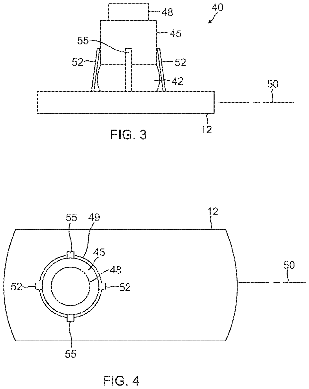
embodiment 40
[0046]Referring to FIGS. 3 and 4 there is shown an alternative embodiment 40 of the ankle joint 13. As shown, this alternative embodiment includes a generally spherical ball 42 to facilitate motion between the foot element 12 and a joint element 45 disposed adjacent the foot element 12. The joint element 45 is fabricated using a three-dimensional printer. The joint element 45 forms a recess at one end shaped to accept a portion of the ball 42. An opposing end of the joint element 45 forms a protrusion 48 configured to fit into the recess in an adjacent modular limb element 20. The foot element 12 similarly defines a depression shaped to accept a portion of the ball 42 opposite the portion of the ball disposed in the joint element 45. Pivotal motion, preferably in approximately a single plane generally parallel to a longitudinal axis 50 of the foot element 12, is achieved by inclusion of two pairs of flexible connectors respectively attached at opposing ends to the foot element 12 an...
embodiment 158
[0060]Referring to FIGS. 16a and 16b there is shown the cover 170 for the prosthetic hand embodiment 158 of the present invention. The cover may, but need not, entirely cover the entirety of the base 160. One preferred embodiment of the cover 170 shown in FIGS. 16a and 16b includes struts 178 to attach the cover to the base 160 and further position the cover 170 above components having moving parts, such as for example the actuators 172, mounted on the base 160. The cover 170 may further form an indentation 179 within which to mount user controls to signal the controller to activate the actuators 172 and effectuate opening or closing of the prosthetic fingers 165 and thumb 168.
[0061]Referring to FIGS. 17a, 17b and 17c there is illustrated several views of a modular finger element 180 of the present invention. The finger element 180 forms at one end a ridge 182 and forms at an opposing end a slot 185 spaced to accommodate the ridge 18 of an adjacent finger element in a sliding relati...
PUM
 Abstract
Description
Claims
Application Information