Injection device

a technology of injection device and needle, which is applied in the direction of medical syringes, infusion syringes, ampoule syringes, etc., can solve the problems of tiresome operation of the injection device, increased viscosity of substances, and thinner gauge size of needles, so as to facilitate and ergonomic operation for users

Pending Publication Date: 2021-07-15
GALDERMA SA
View PDF0 Cites 3 Cited by
  • Summary
  • Abstract
  • Description
  • Claims
  • Application Information

AI Technical Summary

Benefits of technology

[0006]To better address this concern, in a first aspect of the invention there is presented an injection device comprising a drive mechanism, the drive mechanism comprising a drive rod being axially moveable, a plunger rod being axially moveable, and a gear assembly. The gear assembly is arranged such that an axial movement of the drive rod generates an axial movement of the plunger rod. The gear assembly allows for a force transmission between the drive rod and the plunger rod, such that a force applied to the drive rod is transmitted and reinforced by the gear assembly to the plunger rod. This facilitates expelling viscous substances from an injection device without having to apply an excessive input force to the drive rod.
[0007]In accordance with an embodiment of the injection device, the axial movement of the drive rod generates an axial movement of the plunger rod in the same direction. This allows for the injection device to be operable as a traditional handheld syringe, expelling a substance contained therein by moving the drive rod in an axial direction of the injection device towards the patient receiving the expelled substance.
[0010]In accordance with an embodiment of the injection device, a circumference of the drive cogwheel is smaller than a circumference of the plunger cogwheel, the circumference of the plunger cogwheel being in engagement with the circumference of the drive cogwheel. A small circumference of the drive cogwheel allows for a compact injection device. The engagement of the circumference of the drive cogwheel with the circumference of the plunger cogwheel, allows arranging the drive rod and the plunger rod at different sides of the axis around which the plunger cogwheel rotates. This provides for an advantageous centralised distribution of the drive rod and the plunger rod, without the two parts interfering with each other. In this embodiment, the axial movement of the plunger rod, in engagement with the plunger cogwheel, generated by the axial movement of the drive rod, in engagement with the drive cogwheel, will be in the same direction as the axial movement of the drive rod.
[0012]In accordance with an embodiment of the injection device, the first wheel element is rotatable with respect to the second wheel element in one direction only. Due to the force transmission from the drive rod to the plunger rod through the gear assembly, as the drive rod is moved a certain axial distance, a movement of the plunger rod of a shorter axial distance is generated. The first wheel element being rotatable with respect to the second wheel element in one direction only allows returning the drive rod to its initial position by moving it in an axial direction opposite to a substance expelling direction, in which the movement causes substance to be expelled from the injection device, without also moving the plunger rod. Thereby the length of the drive rod does not need to be longer than that of the plunger rod.
[0015]In accordance with an embodiment of the injection device, the drive cogwheel and the plunger cogwheel are arranged on the same axis. In this embodiment, the arrangement of the drive cogwheel and the plunger cogwheel is such that a movement of the drive rod in an axial direction generates a rotation of both cogwheels in the same direction and at the same angular rate, whereby a movement of the plunger rod in an axial direction is generated. This allows arranging the drive rod and the plunger rod at the same side of the axis on which the drive cogwheel and the plunger cogwheel are arranged and around which they rotate, thereby providing a compact injection device.
[0019]In accordance with an embodiment of the injection device, the drive mechanism is arranged at a finger grip of the injection device. Arranging the drive mechanism at a finger grip of the injection device allows for an injection device which is easy and ergonomic for the user to operate.

Problems solved by technology

However, in some areas of application, such as for example fillers of different kinds, the viscosity of the substances has gradually increased over the years and, also, the gauge size of needles has become thinner.
This can be tiresome for a person operating the injection device, and particularly so when the operation time is lengthy.
This drug delivery system is rather complex comprising multiple components which interact to inject a certain dose of a substance.
The drug delivery system is also rather bulky.

Method used


Image

  • Injection device
  • Injection device
  • Injection device

Examples


Embodiment Construction

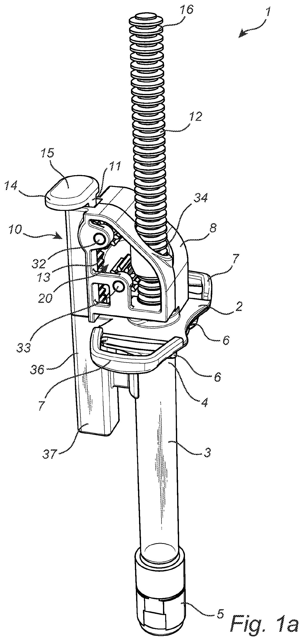
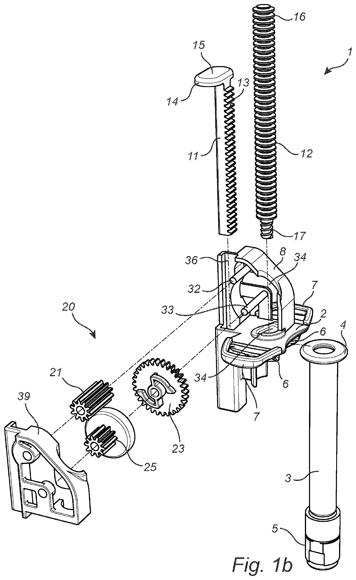
[0028]Referring to FIGS. 1a-b, there is provided an injection device 1 comprising a finger grip 2 and a cartridge 3. The cartridge 3 comprises a proximal end 4 and a distal end 5, the distal end 5 being that oriented towards a patient receiving an injection from the injection device 1. The distal end 5 of the cartridge 3 thus comprises a portion adapted to hold an injection needle, not shown. The cartridge 3 further comprises a plunger (not shown) which upon application of a pressure thereto in a direction towards the distal end 5 of the cartridge, which hereinafter also will be referred to as a substance expelling direction, acts to expel a substance contained in the cartridge 3.

[0029]Generally, any longitudinal part of the injection device 1 which extends in a direction parallel to the cartridge 3 will be considered to comprise a distal end, being that arranged closest to the distal end 5 of the cartridge 3, and a proximal end, being that arranged furthest away from the distal end...


PUM


Abstract

An injection device includes a drive mechanism, and the drive mechanism in turn includes a drive rod being axially moveable, a plunger rod being axially moveable, and a gear assembly. The gear assembly is arranged such that an axial movement of the drive rod generates an axial movement of the plunger rod. This allows for a force transmission between the drive rod and the plunger rod, facilitating the expelling of viscous substances from the injection device.

Description

CROSS-REFERENCE TO RELATED APPLICATION(S)[0001]The present application is a continuation of and claims the benefit of priority to International Application No. PCT / IB2019 / 058149 filed Sep. 25, 2019, which claims the benefit of priority to European Patent Application No. 18196934.6 filed Sep. 26, 2018, the entire contents of which are incorporated herein by reference.FIELD OF THE INVENTION[0002]The present invention relates to an injection device for delivering liquid compositions.BACKGROUND OF THE INVENTION[0003]Injection devices are commonly used for injection of all kinds of liquid substances. However, in some areas of application, such as for example fillers of different kinds, the viscosity of the substances has gradually increased over the years and, also, the gauge size of needles has become thinner. This has a major impact on the force required for extruding the substances. High viscosity of a substance and thin gauge sizes of a needle generally requires application of a high...

Claims


Application Information

Patent Timeline
Patent Type & Authority Applications(United States)
IPC IPC(8): A61M5/315
CPCA61M5/3158A61M2005/3139A61M5/24A61M5/3137A61M5/31511A61M5/31543A61M5/31575A61M5/31578A61M2005/3152
Inventor KARLSSON, HENRIKÖHRLUND, ÅKE
Owner GALDERMA SA
Why Eureka
Try Eureka