Airfield tie-down with deployable talons

Active Publication Date: 2021-07-15
UNITED STATES OF AMERICA THE AS REPRESENTED BY THE SEC OF THE ARMY
View PDF0 Cites 2 Cited by
  • Summary
  • Abstract
  • Description
  • Claims
  • Application Information

AI Technical Summary

Benefits of technology

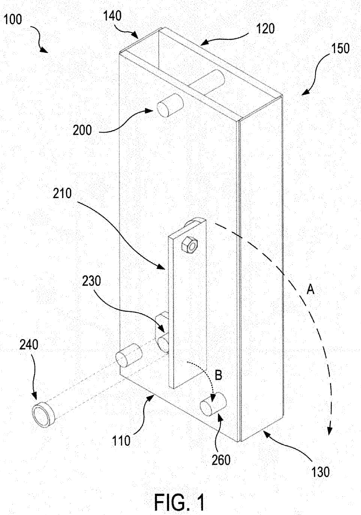
The present invention introduces a new tie-down assembly that can replace existing devices. This tie-down device is versatile, adaptable, and effective, being suitable for various thicknesses of concrete slabs or pavements. Additionally, it is easy to install and can be quickly adapted to different types of aircraft mooring areas or aviation field parking platforms. Overall, this tie-down device offers a more efficient and flexible solution for securing aircraft in parking areas.

Problems solved by technology

However, in certain circumstances, such as during wartime, it may not be possible to know in advance the thickness of the concrete slab where the aircraft are parked.
In contrast, other currently known tie-downs may require a larger area of pavement due to their size and installation method parameters.
Other known tie-down designs are not adjustable once on site, nor can they be adjusted from their original design to account for variation in pavement thickness.
What is more, other known designs may not brace against the base of the parent slab and therefore have little or no vertical pullout resistance.

Method used


Image

  • Airfield tie-down with deployable talons
  • Airfield tie-down with deployable talons
  • Airfield tie-down with deployable talons

Examples


Embodiment Construction

[0018]Detailed illustrative embodiments of the present invention are disclosed herein. However, specific structural and functional details disclosed herein are merely representative for purposes of describing example embodiments of the present invention. The present invention may be embodied in many alternate forms and should not be construed as limited to only the embodiments set forth herein. Further, the terminology used herein is for the purpose of describing particular embodiments only and is not intended to be limiting of example embodiments of the invention.

[0019]As used herein, the singular forms “a.”“an,” and “the,” are intended to include the plural forms as well, unless the context clearly indicates otherwise. It further will be understood that the terms “comprises,”“comprising,”“includes,” and / or “including,” specify the presence of stated features, steps, or components, but do not preclude the presence or addition of one or more other features, steps, or components. It ...


PUM


Abstract

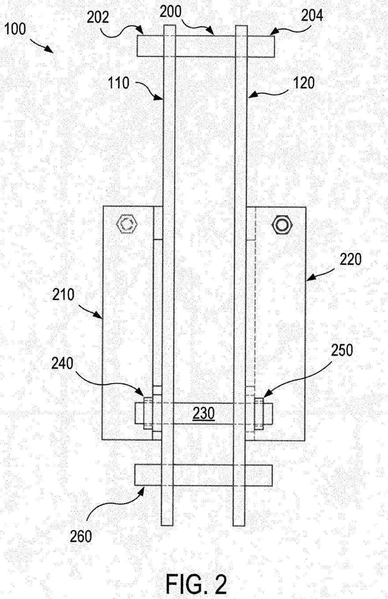
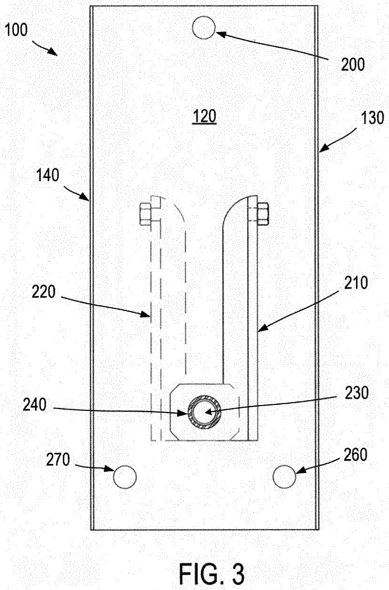
In one embodiment, tie-down assembly is provided for securing a parked aircraft to a slab of an aircraft mooring area. The assembly includes a support structure having a first side wall, a second side wall, a first end cover coupled with the first side wall and the second side wall, and a second end cover coupled with the first side wall and the second side wall. The assembly also includes a connector rod coupled with the first side wall and the second side wall, a talon pivot rod coupled with the first side wall and the second side wall, a first talon rotatably coupled with the talon pivot rod, a second talon rotatably coupled with the talon pivot rod, a first depth adjustment mechanism coupled with the first talon, and a second depth adjustment mechanism coupled with the second talon.

Description

STATEMENT OF GOVERNMENT INTEREST[0001]Under paragraph 1(a) of Executive Order 10096, the conditions under which this invention was made entitle the Government of the United States, as represented by the Secretary of the Army, to an undivided interest therein on any patent granted thereon by the United States. This and related patents are available for licensing to qualified licensees.BACKGROUNDField of the Invention[0002]The present invention relates to anchoring techniques, and, more particularly but not exclusively, to tie-down devices and methods that can be used to secure a parked aircraft against movement.DESCRIPTION OF THE RELATED ART[0003]This section introduces aspects that may help facilitate a better understanding of the invention. Accordingly, the statements of this section are to be read in this light and are not to be understood as admissions about what is prior art or what is not prior art.[0004]Tie-down systems are well known in the aircraft industry. Airports and oth...

Claims


Application Information

Patent Timeline
IPC IPC(8): B64F1/16
CPCB64F1/16
Inventor HOFFMAN, NOLAN R.
Owner UNITED STATES OF AMERICA THE AS REPRESENTED BY THE SEC OF THE ARMY
Why Eureka
Try Eureka