Stereo display for position sensing systems

Inactive Publication Date: 2007-11-27
EASTMAN KODAK CO
View PDF65 Cites 19 Cited by
  • Summary
  • Abstract
  • Description
  • Claims
  • Application Information

AI Technical Summary

Benefits of technology

[0018]It is an advantage of the present invention that it provides an effective way to adapt radar for viewing in three dimensions. This data can then be used to provide a stereoscopic visualization of detected objects, using any of a number of stereoscopic and autostereoscopic displays.

Problems solved by technology

For this type of application, however, the limitations of the conventional CRT display are most readily apparent.
As air traffic continues to grow in volume, there are increased risks for mistakes that can jeopardize life and property.
As a further drawback, conventional display methods do not indicate aircraft 12 direction on an instantaneous basis; this data must be inferred from observation.

Method used


Image

  • Stereo display for position sensing systems
  • Stereo display for position sensing systems
  • Stereo display for position sensing systems

Examples


Embodiment Construction

[0036]The present description is directed in particular to elements forming part of, or cooperating more directly with, apparatus in accordance with the invention. It is to be understood that elements not specifically shown or described may take various forms well known to those skilled in the art.

Forming a Stereoscopic Image

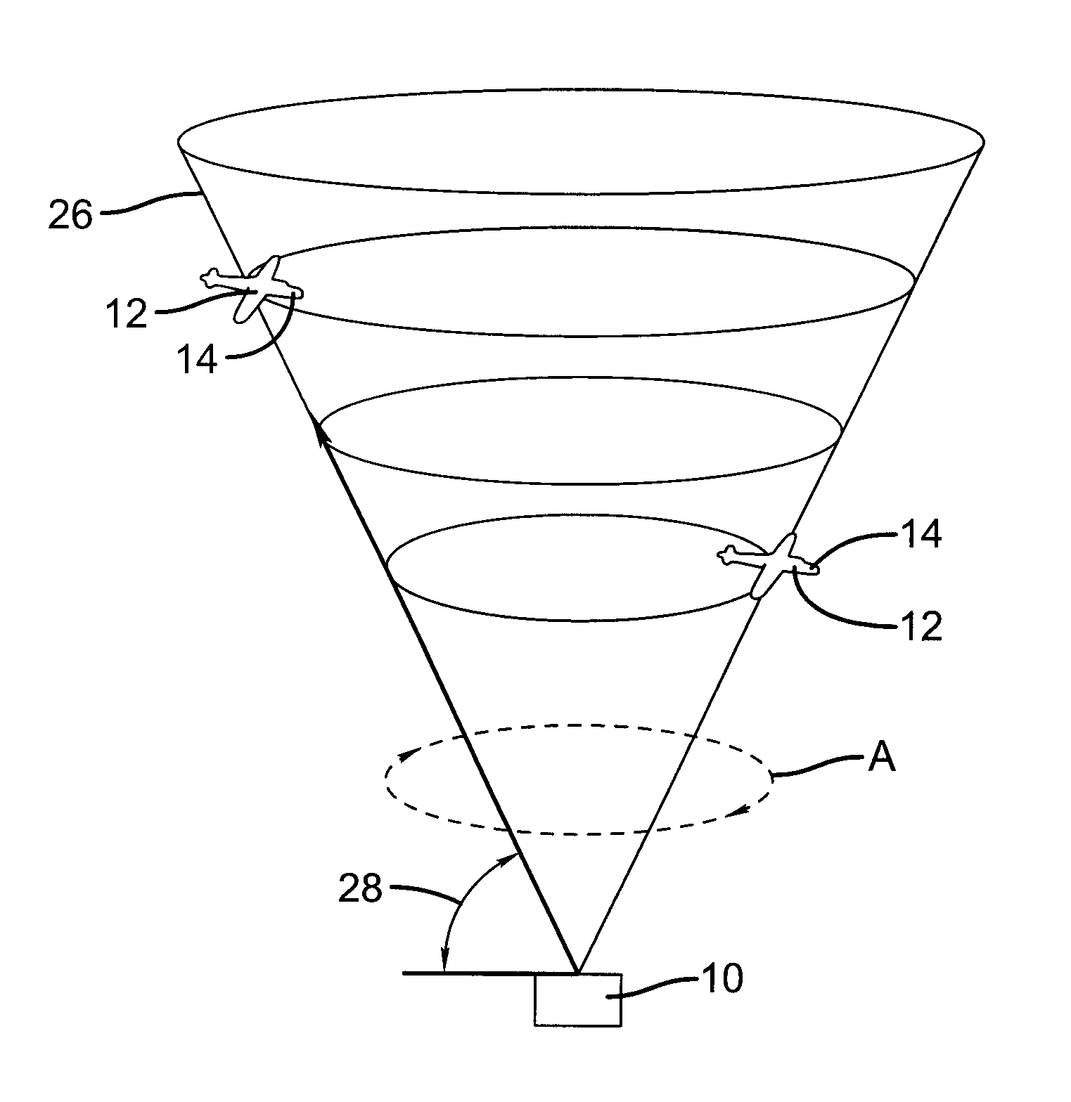
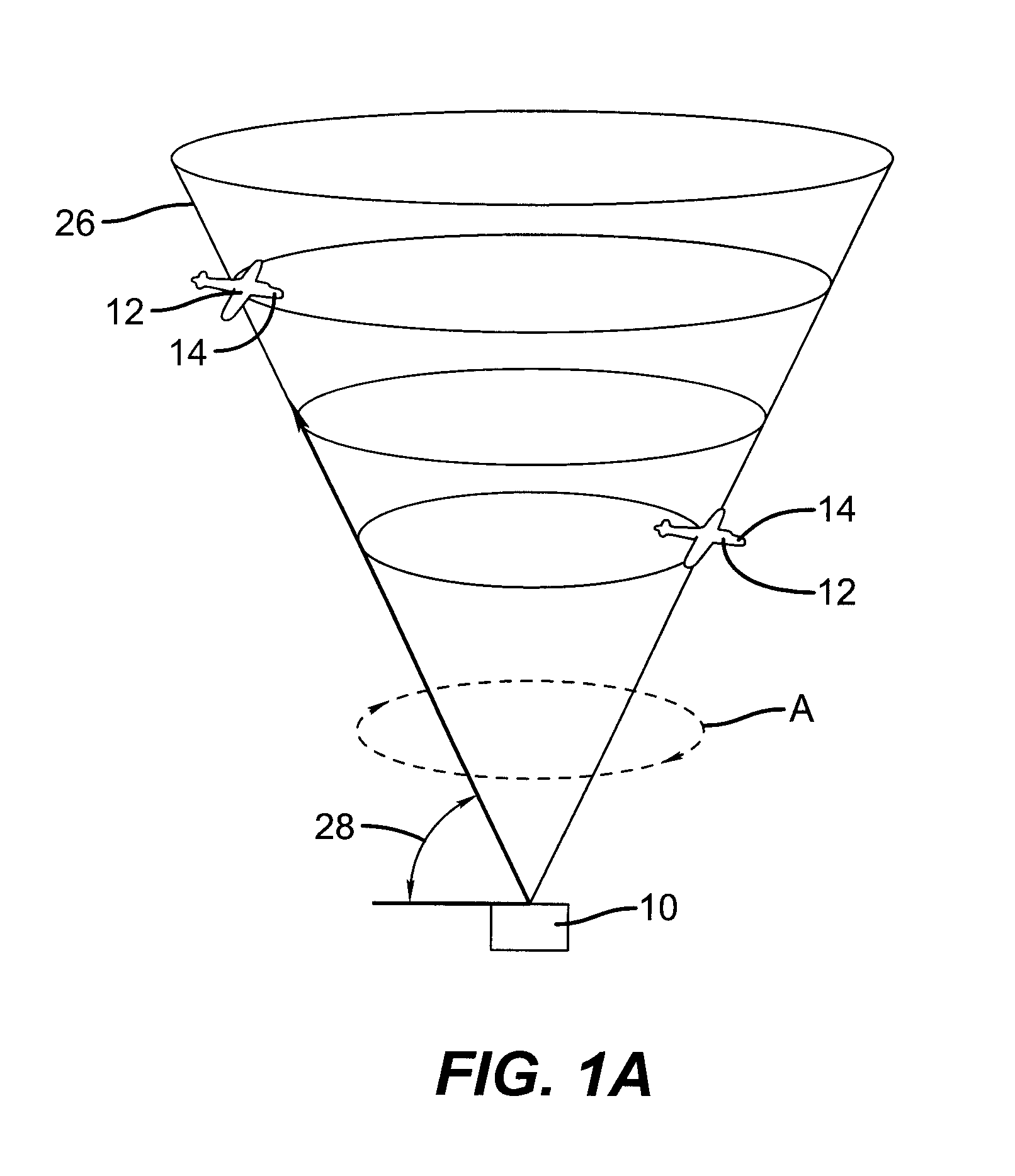
[0037]The present invention uses radar data from successive scans along with related tracking apparatus data in order to generate a stereoscopic image. In order to better understand the operation of the present invention, it is first useful to review how stereoscopic images are formed.

[0038]The term “stereoscopic image” implies that a pair of images is formed: one right eye image and one left eye image. This pair of images can be more precisely termed as a stereoscopic pair of images. For the description that follows, the term stereoscopic image can be considered to be equivalent to a stereoscopic pair of images.

[0039]As a general principle, a stereoscopic image...


PUM


Abstract

A method for display of radar data includes performing a first radar scan to obtain, for at least one object (24), a first range reading, a first azimuth reading, and a first altitude reading. A second radar scan is then performed to obtain, for the at least one object (24), a second range reading, a second azimuth reading, and a second altitude reading. Position and travel direction of the at least one object (24) are computed within a predetermined cylindrical volume (20), according to readings from the first and second radar scans. An icon (34) is assigned to the at least one object (24). A reference point (R) is determined for the predetermined cylindrical volume. The icon (34) is then displayed within the predetermined cylindrical volume (20) in stereoscopic form.

Description

FIELD OF THE INVENTION[0001]This invention relates to stereoscopic displays and more particularly relates to a display apparatus and method for stereoscopic presentation of position-sensing data.BACKGROUND OF THE INVENTION[0002]Various types of radar systems are used in government and military applications, such as for early warning devices that show the approach of aircraft, missiles, ships, and land vehicles. Conventionally, a flat, circular CRT serves as the radar display, showing dots or “blips” for detected objects, updated with each sweep of the radar signal. Fiducial “rings” on the CRT surface help to indicate range increments. For many types of applications, this type of two-dimensional display has proved sufficiently usable for skilled operators who can interpret the displayed data.[0003]Civilian air traffic control systems also use radar as a means for tracking and guiding aircraft movement. For this type of application, however, the limitations of the conventional CRT dis...

Claims


Application Information

Patent Timeline
IPC IPC(8): G01S13/00
CPCG01S7/20G01S13/87
Inventor RODDY, JAMES E.BARNICK, WILLIAM M.
Owner EASTMAN KODAK CO
Why Eureka
Try Eureka