
Charging device for a physiological signal transmitter and a charging method for the same

a charging device and transmitter technology, applied in the direction of telemetric patient monitoring, coupling device connection, safety/protection circuit, etc., can solve the problems of reducing the service life of the transmitter, etc., to prevent the damage of the charger or the transmitter, prevent improper impact, and prevent the effect of foiling

Active Publication Date: 2021-07-15
BIONIME
View PDF0 Cites 1 Cited by
  • Summary
  • Abstract
  • Description
  • Claims
  • Application Information

AI Technical Summary

Benefits of technology

The present invention is designed to prevent damage to the charger or transmitter caused by incorrect placement of the transmitter on the charger. It provides power to the transmitter and ensures that the electrical connection is secure and foolproof. Additionally, the invention has safety mechanisms to prevent improper impact caused by movement of the charging connector and to prevent the transmitter from shaking or falling out on the charger. The charger also has a positioning mechanism to block the transmitter and prevent it from easily detaching from the charger.

Problems solved by technology

In addition, because the CGM system must be worn by the user for a long time, the miniaturization of the device has become an inevitable trend.
The transmitter is a relatively expensive electronic element and usually contains the processing element for processing the signal from the transmitter and transmitting the processed signal in a wireless way.

Method used


Image

  • Charging device for a physiological signal transmitter and a charging method for the same
  • Charging device for a physiological signal transmitter and a charging method for the same
  • Charging device for a physiological signal transmitter and a charging method for the same

Examples


Embodiment Construction

[0050]The present invention will now be described more specifically with reference to the following embodiments. It is to be noted that the following descriptions of preferred embodiments of this invention are presented herein for the purposes of illustration and description only; they are not intended to be exhaustive or to be limited to the precise form disclosed.

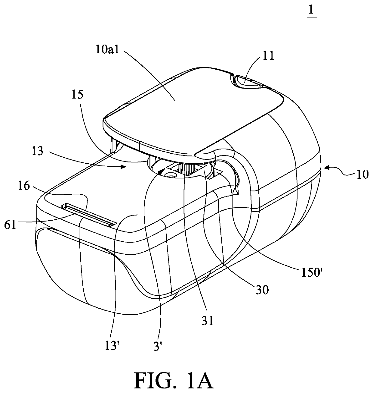
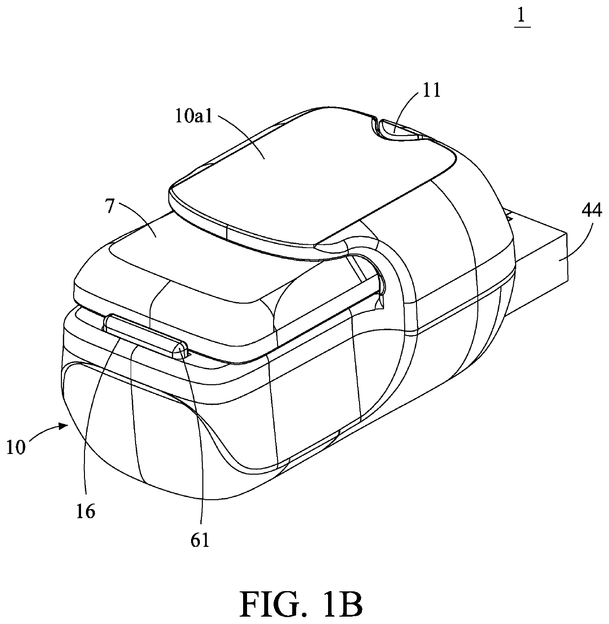
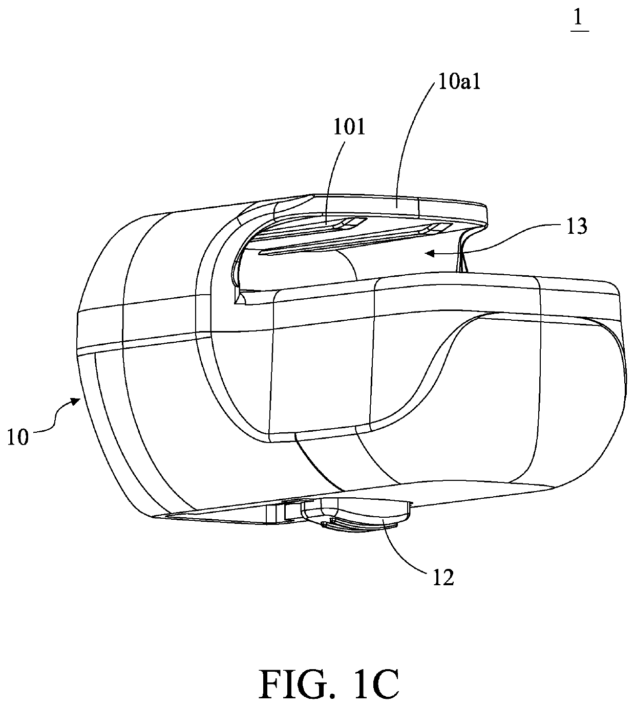
[0051]Please refer to FIGS. 1A-1G. FIGS. 1A-1D are presented at different angles to fully show the relative positions and connecting relationships among elements and structures. As shown in FIGS. 1A-1D, a charging device 1 has a main body 10, usually a shell-shaped object, for disposing and protecting the required elements and structures therein. The charging device 1 also has a placing portion 13 having a bearing surface 13′ for placing the physiological signal transmitter 7 (hereinafter referred to as the transmitter 7). The placing portion 13 is similar to a slot or a pocket-like structure, and formed by a cover plate ...


PUM


Abstract

A charging device for a physiological signal transmitter used to receive a physiological signal from the subcutaneous tissue of a living body and having a first electrical connecting port is disclosed. The charging device includes a transmitter placing seat and a charging module. The transmitter placing seat includes a bearing surface for placing the physiological signal transmitter and an opening configured to align with the first electrical connection port of the physiological signal transmitter. The charging module includes a second electrical connecting port, a third electrical connecting port, a circuit assembly and a control module. The second electrical connecting port is disposed in the opening, and driven to move between a first position and a second position. The third electrical connecting port connects to a power source.

Description

CROSS-REFERENCE TO RELATED APPLICATION AND CLAIM OF PRIORITY[0001]The application claims the benefit of the U.S. Provisional Application No. 62 / 960,855, filed on Jan. 14, 2020, at the USPTO, the disclosures of which are incorporated herein in their entirety by reference.FIELD OF THE INVENTION[0002]The present invention relates to a charging device, and more particularly to a charging device applied to a transmitter. The transmitter is a reusable electronic device for collecting physiological signals of the living body and transmitting them out in a continuous physiological signal measuring device, and the charging device is used to charge the transmitter.BACKGROUND OF THE INVENTION[0003]With the recent advancements of current technology and changing lifestyles, some tests which had to be tested in the hospital in the past have now changed to home measurement. In particular, the change in lifestyles has led to an increase in patients with chronic diseases, which has accelerated the d...

Claims


Application Information

Patent Timeline
Patent Type & Authority Applications(United States)
IPC IPC(8): H01R13/642H02J7/00H01R13/66H01R13/631H01R33/945H01R43/26
CPCH01R13/642H02J7/0045H01R13/665H01R13/631A61B5/14503H01R33/945H01R43/26H01R2201/12H01R13/6675H05K5/0208A61B5/14532H05K5/061B01D53/26A61B2560/063A61B2560/0204A61B2560/0456A61B2560/045A61B5/002A61B2562/18A61B2562/242H02J2310/23H02J7/0044H02J7/02A61B5/150877A61B5/0002A61B5/155A61B2560/0219G16H20/17A61M5/1723A61M2205/35A61M2205/8237A61M2205/8262A61B5/0031A61B5/073H02J7/0031G16H40/67A61B5/0004A61B5/0015A61B2562/227H01R13/639A61B5/6801A61B5/72A61B2562/166
Inventor CHEN, CHIEH-HSINGHUANG, CHUN-MU
Owner BIONIME
Learn More