Method for making a handle for an electrically operated personal care implement

a technology of personal care implements and handles, which is applied in the field of manufacturing a handle for an electrically operated personal care implement, can solve the problems of limited bonding area between the components, gaps allowing water to enter the inner part of the housing, and insufficient bonding force between the switch area/element and the metal tube to withstand regular stress

Pending Publication Date: 2021-07-22
THE GILLETTE CO +1
View PDF0 Cites 13 Cited by
  • Summary
  • Abstract
  • Description
  • Claims
  • Application Information

AI Technical Summary

Benefits of technology

This patent describes a method for making a handle for a personal care implement that is powered by electricity. The handle is made by attaching a hard switch component to a metal tube housing and then over-molding the opening to form a soft switch component. This process creates a sealed opening that is activated by the hard switch component to power the personal care implement. The technical effect of this invention is a more reliable and durable handle for electrically operated personal care implements that can be easily gripped and used.

Problems solved by technology

It has been found out that such metal housings bring new challenge in creating a waterproof switch area.
Due to the relatively thin wall thickness and reduced freedom in designing the housing (the metal housing is not freeformed as usual plastic parts, but have the form of a simple metal tube), the bonding area between the components is limited and a let-in flush switch area / element cannot be simply overmolded onto the housing.
The bonding force between the switch area / element and the metal tube is not sufficient to withstand regular stress occurring during use of the switch.
Peel stress in the bonding area weakens the bonding connection which may result in gaps allowing water entering the inner part of the housing.
A durable waterproof handle housing cannot be provided by such design.

Method used


Image

  • Method for making a handle for an electrically operated personal care implement
  • Method for making a handle for an electrically operated personal care implement
  • Method for making a handle for an electrically operated personal care implement

Examples


Embodiment Construction

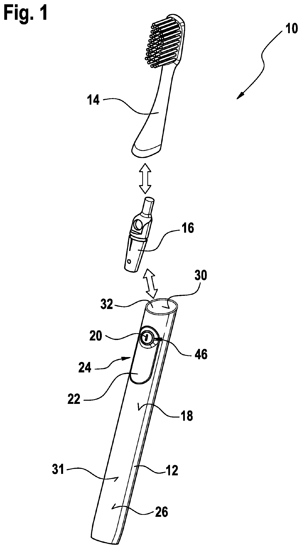
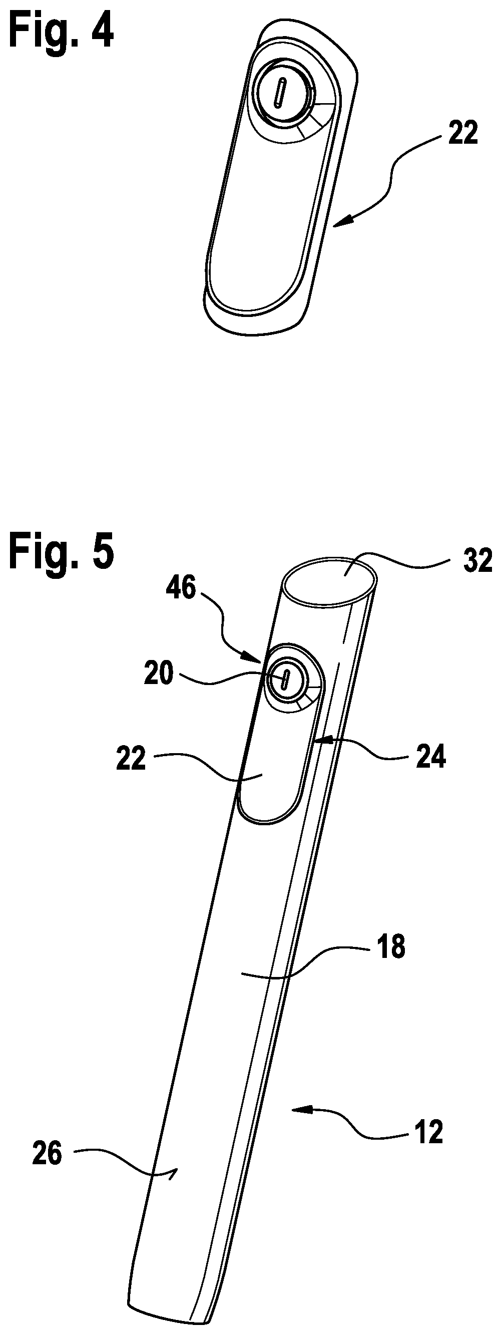
[0025]The method for manufacturing a handle for an electrically operated personal care implement comprises the provision of a metal tube housing, the housing having a metal wall with an opening therein and an inner surface, the inner surface defining an inner cavity for accommodating an energy source for operating the personal care implement. The opening, e.g. a cut-out which may be provided by laser cutting, to accommodate a switch assembly for activating the energy source, i.e. for switching the electronically operated personal care implement to an ON / OFF status. Said switch assembly for operating the implement comprises a hard switch component and a soft switch component; the hard switch component comprises a frame with a recess.

[0026]In order to provide the metal tube housing with the switch assembly, the method according to the present disclosure comprises: providing a hard switch component comprising a frame with a recess, and attaching the frame of the hard switch component t...


PUM

PropertyMeasurementUnit
Timeaaaaaaaaaa
Pressureaaaaaaaaaa
Elastomericaaaaaaaaaa

Abstract

A method for manufacturing a handle for an electrically operated personal care implement comprises the following steps: providing a metal tube housing having a metal wall with an opening therein and an inner surface defining an inner cavity for accommodating an energy source; providing a hard switch component comprising a frame with a recess; attaching the frame of the hard switch component to the inner surface of the metal wall, the frame surrounding the opening and providing an undercut between the recess and the inner surface, the undercut being open towards the opening; and at least partially over-molding the opening to form a soft switch component in the undercut, thereby forming with the hard switch component a switch assembly for activating the energy source, the switch assembly sealing the opening from the inner surface of the metal wall.

Description

FIELD OF THE INVENTION[0001]The present disclosure is concerned with a method for manufacturing a handle for an electrically operated personal care implement. The present disclosure is further concerned with a handle for an electrically operated personal care implement manufactured by such method.BACKGROUND OF THE INVENTION[0002]Personal care implements, like toothbrushes, are well known in the art. Generally, tufts of bristles for cleaning teeth are attached to a bristle carrier or mounting surface of a brush head intended for insertion into a user's oral cavity. A handle is usually attached to the head, which handle is held by the user during brushing. Usually, heads of manual toothbrushes are permanently connected to the handle, e.g. by injection molding the bristle carrier, the handle, a neck connecting the head and the handle, in one injection molding step. After the usual lifetime of a toothbrush, i.e. after about three months of usage, the toothbrush is discarded. In order to...

Claims


Application Information

Patent Timeline
IPC IPC(8): A61C17/22B29C45/16
CPCA61C17/225B29L2031/425B29C45/1676B29C45/14336B29C66/028B29C66/02245B29C65/48B29C45/0001B29C66/72321B29C66/742B29C45/14008
Inventor JUNGNICKEL, UWEBRUST, MARTINKNORR, MARCEL DENISREUSCHENBACH, ANDREASMORGOTT, MARKUS
Owner THE GILLETTE CO
Why Eureka
Try Eureka