Eyedropper bottle holder

a bottle holder and eyedropper technology, applied in the field of bottle holders, can solve the problems of affecting the effect of eye drops, and affecting the use of eye drops, and achieve the effect of greatly enhancing the administration of eye drops

Pending Publication Date: 2021-07-22
SAVIOLA JAMES F
View PDF4 Cites 3 Cited by
  • Summary
  • Abstract
  • Description
  • Claims
  • Application Information

AI Technical Summary

Benefits of technology

[0006]The present invention relates to the discovery that administration of eye drops is enhanced greatly by mounting the eyedropper bottle on a de

Problems solved by technology

However, there is great difficulty in terms of using it to then instill the drop properly without touching the eye or eyelid, or otherwise one ends up making a mess.
There are both disposable devices and reusable devices known in

Method used


Image

  • Eyedropper bottle holder
  • Eyedropper bottle holder
  • Eyedropper bottle holder

Examples


Embodiment Construction

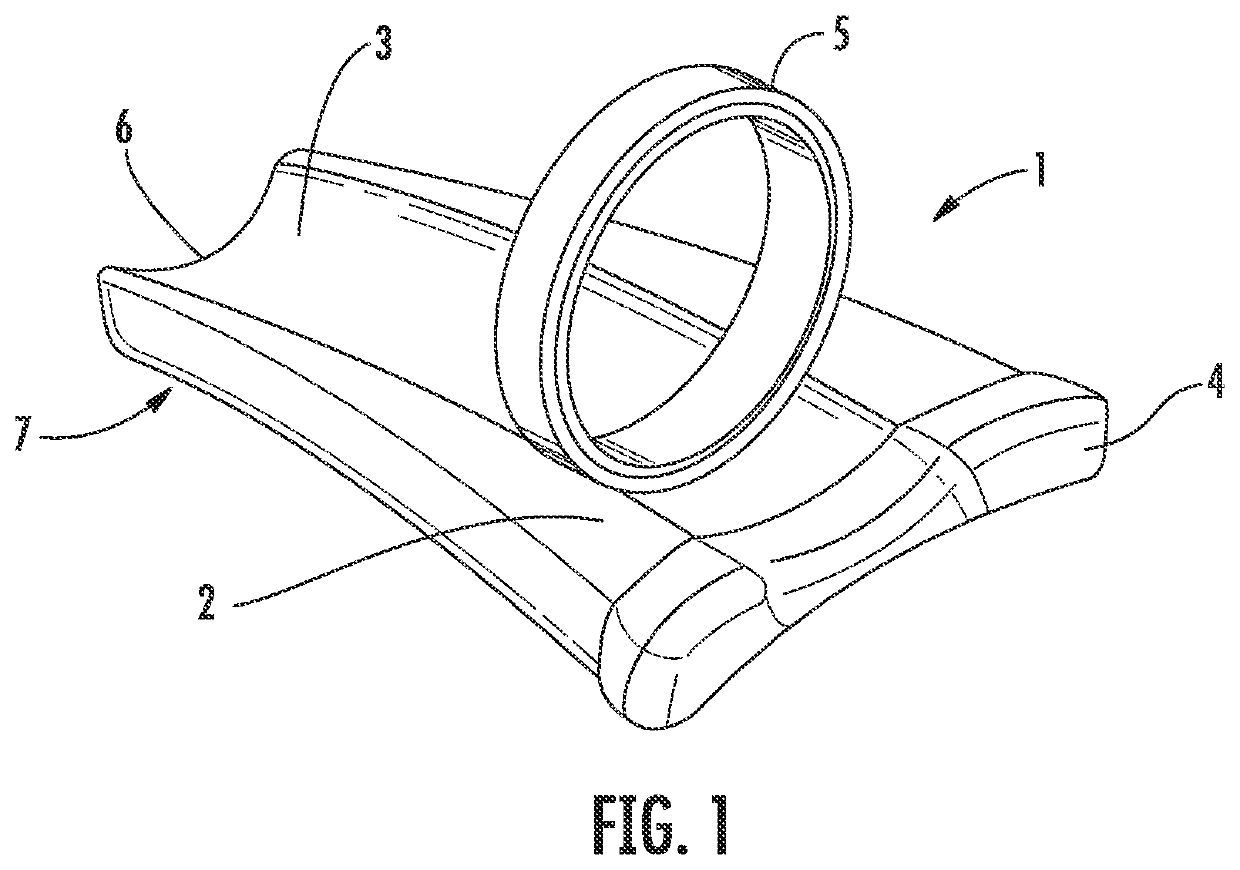
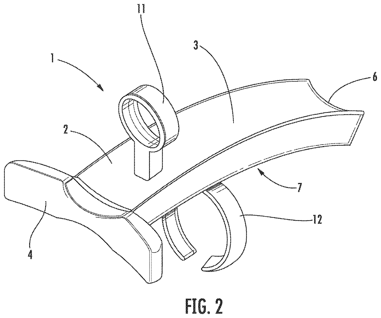
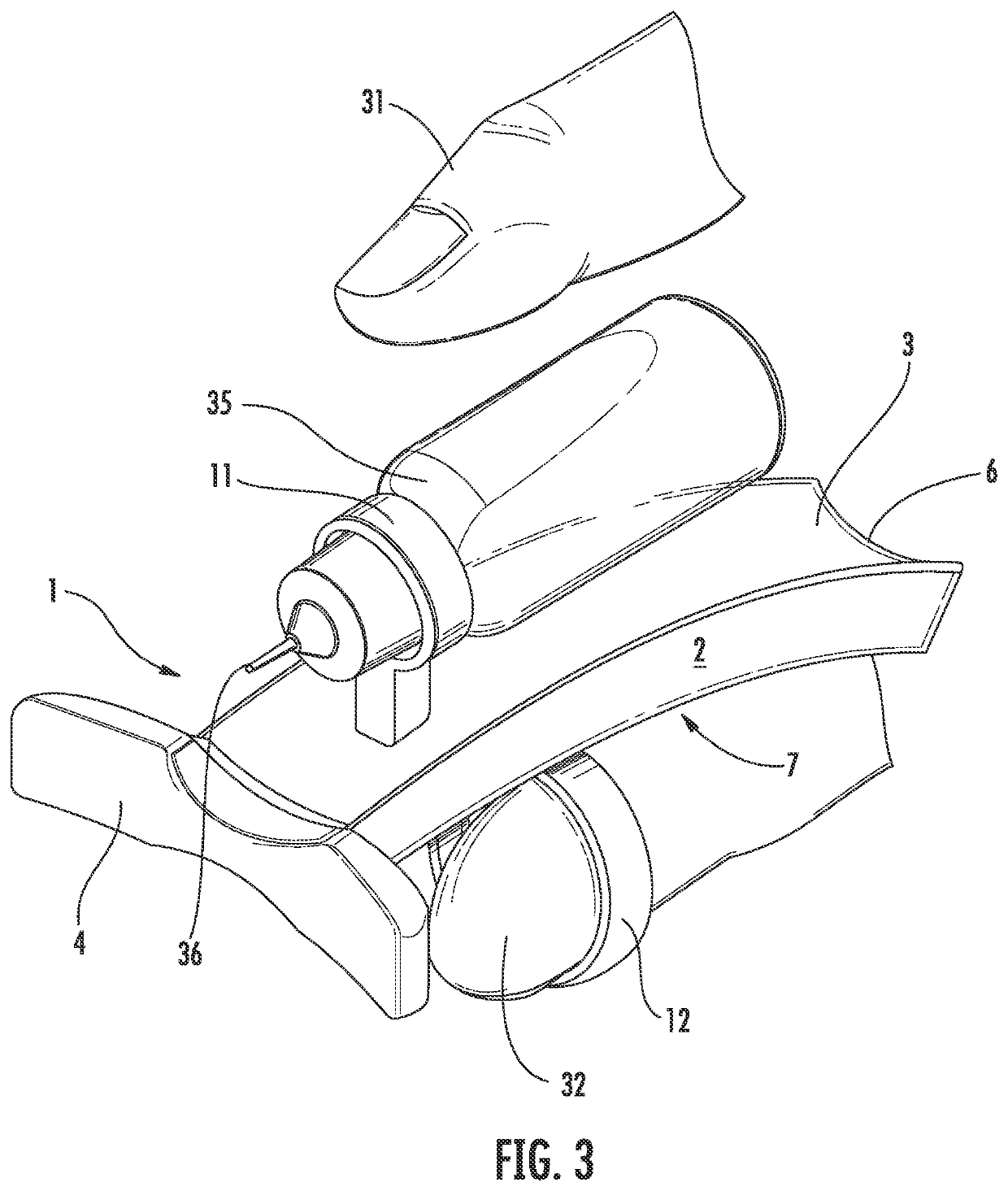
[0027]While this invention is susceptible to embodiment in many different forms, there is shown in the drawings, and will herein be described in detail, specific embodiments with the understanding that the present disclosure of such embodiments is to be considered as an example of the principles and not intended to limit the invention to the specific embodiments shown and described. In the description below, like reference numerals are used to describe the same, similar, or corresponding parts in the several views of the drawings. This detailed description defines the meaning of the terms used herein and specifically describes embodiments in order for those skilled in the art to practice the invention.

DEFINITIONS

[0028]The terms “about” and “essentially” mean±10 percent.

[0029]The terms “a” or “an”, as used herein, are defined as one or as more than one. The term “plurality”, as used herein, is defined as two or as more than two. The term “another”, as used herein, is defined as at le...


PUM


Abstract

The present invention is a device for holding an ophthalmic bottle of drops and instilling them in a patient's eye. The device rests on the boney lower orbital ridge for stability and correct delivery.

Description

[0001]This application is a continuation-in-part of U.S. non-provisional application Ser. No. 16 / 546,589 filed on Aug. 21, 2019, which is a continuation-in-part of U.S. non-provisional application Ser. No. 15 / 151,579 filed on May 11, 2016 now U.S. Pat. NO. 10,426,660 issued on Oct. 1, 2019, and which are incorporated herein in their entirety by reference.COPYRIGHT NOTICE[0002]A portion of the disclosure of this patent contains material that is subject to copyright protection. The copyright owner has no objection to the reproduction by anyone of the patent document or the patent disclosure as it appears in the Patent and Trademark Office patent files or records, but otherwise reserves all copyright rights whatsoever.BACKGROUND OF THE INVENTIONField of the Invention[0003]The present invention relates to a bottle holder. In particular, it relates to a device for holding an eyedropper bottle and positioning it for use.Description of Related Art[0004]The administration of a drop to the e...

Claims


Application Information

Patent Timeline
IPC IPC(8): A61F9/00
CPCA61F9/0026
Inventor SAVIOLA, JAMES F.
Owner SAVIOLA JAMES F
Why Eureka
Try Eureka