Unlock instant, AI-driven research and patent intelligence for your innovation.

Equipment monitoring system, equipment monitoring method, and recording medium

a technology of equipment monitoring and equipment, applied in the direction of instruments, structural/machine measurement, coin-freed apparatus, etc., can solve the problems of customer satisfaction reduction and opportunity loss

Inactive Publication Date: 2021-07-29
NEC CORP
View PDF0 Cites 0 Cited by
  • Summary
  • Abstract
  • Description
  • Claims
  • Application Information

AI Technical Summary

Benefits of technology

The system described in this patent makes a notification when a failure occurs in equipment, allowing for quick visual confirmation. The purpose is to improve the monitoring of equipment and increase efficiency in identifying and addressing issues.

Problems solved by technology

Such equipment has problems of an opportunity loss due to failure in the equipment and reduction in customer satisfaction (CS).
However, the method of simply making the notification of the coping method has a problem of not knowing which coping method should be adopted in the case where there is a plurality of coping methods.

Method used


Image

  • Equipment monitoring system, equipment monitoring method, and recording medium
  • Equipment monitoring system, equipment monitoring method, and recording medium
  • Equipment monitoring system, equipment monitoring method, and recording medium

Examples


first example embodiment

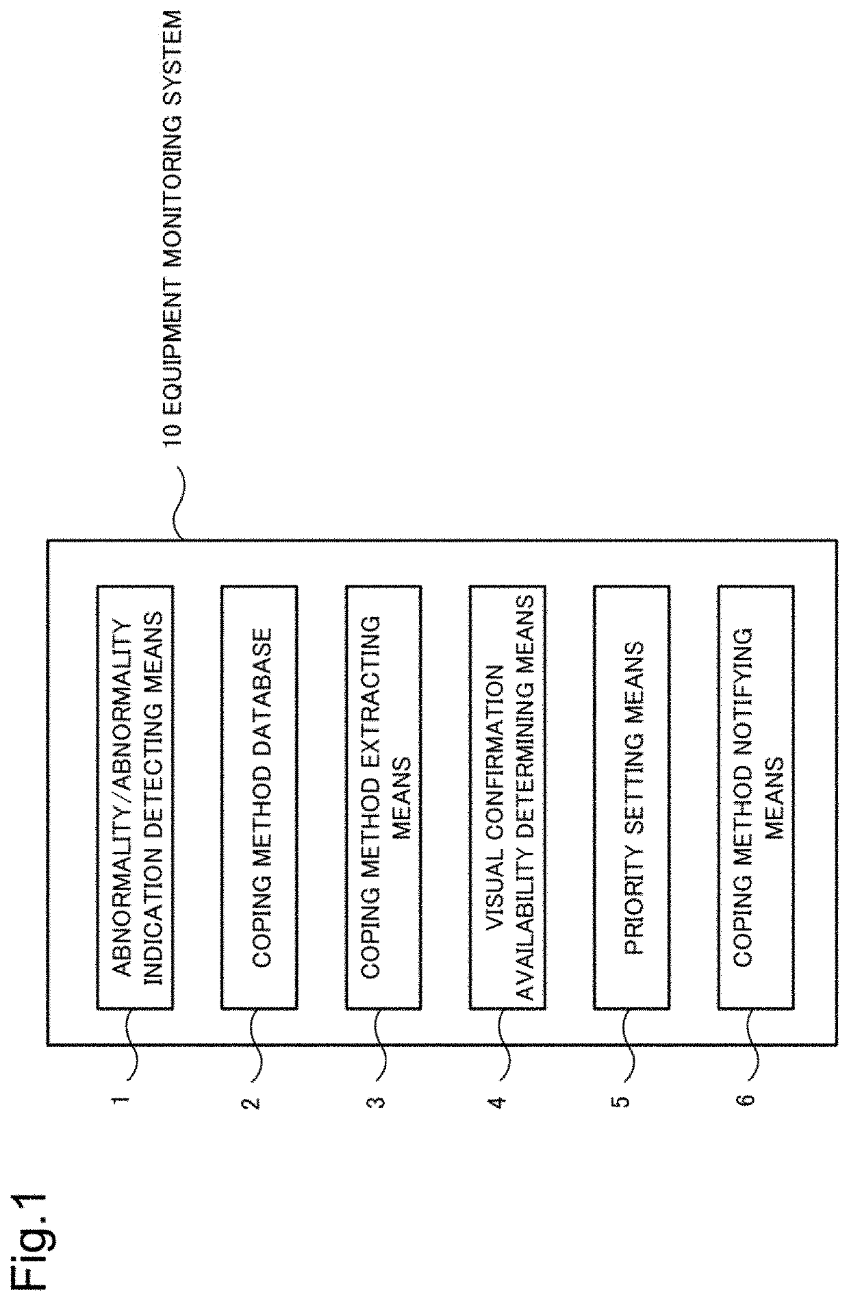
[0035]FIG. 1 is a block diagram illustrating an equipment monitoring system 10 according to a first example embodiment. The equipment monitoring system includes an abnormality or abnormality indication detecting means 1, a coping method database 2, a coping method extracting means 3, a visual confirmation availability determining means 4, a priority setting means 5, and a coping method notifying means 6.

[0036]The abnormality or abnormality indication detecting means 1 detects an abnormality or abnormality indication of equipment. Here, the abnormality indication is assumed to indicate a state in which the equipment is currently in a general state (or normal state) but there is a possibility of occurrence of an abnormal state in the future. The state in which there is a possibility of occurrence of an abnormal state means a state in which an event that is a sign of occurrence of an abnormal state has occurred even in the general state.

[0037]The coping method database 2 stores a copin...

second example embodiment

[0043]FIG. 2 is a block diagram illustrating a hardware configuration of the equipment monitoring system 1000 according to a second example embodiment. The equipment monitoring system 1000 includes a data collector 1100 that collects data from equipment 2000, a computer 1200 that processes the data, a storage device 1300 that stores the data, and an output device 1400.

[0044]FIG. 3 is a block diagram illustrating functional blocks of the equipment monitoring system 1000. An equipment monitoring unit 1210 is mounted on the computer 1200. In the storage device 1300, a coping method database 1310 is implemented. As the output device 1400, for example, a display device 1410, a speaker 1420, a printer 1430, or the like can be used.

[0045]The equipment monitoring unit 1210 includes a data reception unit 1211, an abnormality or abnormality indication detection unit 1212, a coping method extraction unit 1213, a visual confirmation availability determination unit 1214, a priority setting unit ...

specific example 1

[0053]Next, a specific example using a coffee machine installed in a store as equipment will be described. FIG. 5 is a block diagram illustrating a coffee machine monitoring system 1001 of a specific example 1. The coffee machine monitoring system 1001 includes a data collector 1100a, a coffee machine monitoring unit 1210a, a coping method database 1310a, and a display device 1410a. In the present specific example, a current waveform of a coffee machine 2000a collected by a current sensor 1110a is used as the equipment monitoring data. The data collector 1100a samples a current value at predetermined sampling time. The coffee machine monitoring unit 1210a analyzes the current waveform, detects an abnormality or an abnormality indication, and specifies a type of the abnormality or the abnormality indication. The coffee machine monitoring unit 1210a gives an error code to the specified abnormality or abnormality indication.

[0054]FIG. 6 is a diagram illustrating an example of an abnorm...


PUM


Abstract

An equipment monitoring system includes an abnormality / abnormality indication detecting means, a coping method database, a coping method extracting means, a visual confirmation availability determining means, a priority setting means, and a coping method notifying means. The abnormality / abnormality indication detecting means detects an abnormality or an abnormality indication of equipment. The coping method database stores a coping method for the abnormality or the abnormality indication, the coping method including visual confirmation. The coping method extracting means extracts the coping method for the detected abnormality or the detected abnormality indication from the coping method database. The visual confirmation availability determining means determines whether the extracted coping method includes visual confirmation. When there is a plurality of extracted coping methods, the priority setting means sets a high priority to the coping method including visual confirmation. The coping method notifying means makes a notification of the coping method based on the set priority.

Description

CROSS REFERENCE TO RELATED APPLICATIONS[0001]This application is a National Stage of International Application No. PCT / JP2019 / 021508 filed May 30, 2019, claiming priority based on Japanese Patent Application No. 2018-106693 filed Jun. 4, 2018.TECHNICAL FIELD[0002]The some non-limiting embodiments relates to an equipment monitoring system and the like.BACKGROUND ART[0003]In various fields, introduction of equipment for labor saving and manpower saving is progressing. For example, equipment for automating provision of beverages and the like is increasingly introduced into retail stores. Such equipment has problems of an opportunity loss due to failure in the equipment and reduction in customer satisfaction (CS). In other words, reduction of response time when a failure has occurred in equipment is required. To reduce the response time, prompt execution of an effective coping method for the failure is necessary. Therefore, making a notification of the content of the failure and the cop...

Claims


Application Information

Patent Timeline
IPC IPC(8): G01M99/00G06F16/245
CPCG01M99/005G06F16/245G07F13/00G06Q10/00G01M99/00
Inventor OHTA, YUKO
Owner NEC CORP