Transfer Assist Pivot Board

a technology of assist board and pivot board, which is applied in the field of mechanical equipment, can solve the problems of care giver from being close, the risk of patient falling, and the solution was typically too small for a physically challenged person to maintain proper body alignment, so as to reduce the risk of harm to a patient, the effect of smoothly swiveling or pivoting

Active Publication Date: 2021-08-19
TAYLOR ANNA
View PDF0 Cites 0 Cited by
  • Summary
  • Abstract
  • Description
  • Claims
  • Application Information

AI Technical Summary

Benefits of technology

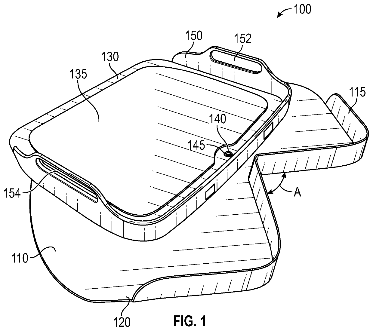
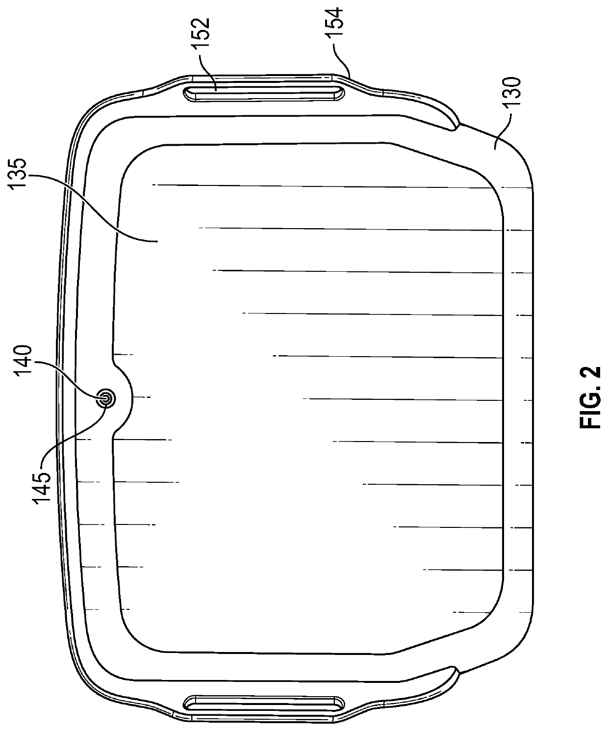
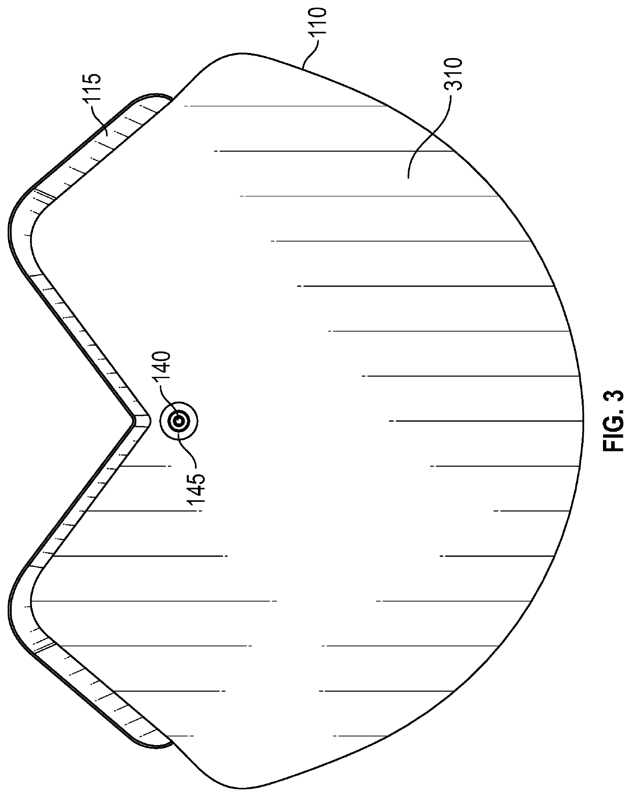
[0005]It is therefore an aim of the present invention to provide a transfer assist board to reduce the risk of harm to a patient during a transfer. The transfer assist board has a base plate with a non-skid under-layer and a pivoting foot plate rotatably mounted to the base plate. The top surface of the foot plate is also provided with a non-skid surface to inhibit the patient's feet from slipping. Recessed wheels mounted to the under-side of the foot plate allow the the foot plate to smoothly swivel or pivot around a pivot point and along the upper surface of the base plate. Stops are provided to constrain the swivel of the foot plate so that it the swivel is limited to a first position and a second position.

Problems solved by technology

During such transfers of location, there is always a risk that the patient will fall.
These solutions were typically too small for a physically challenged person to maintain proper body alignment.
The circular shape of prior devices prevents a care giver from being close to the person to lend adequate assistance because there no space provided for a care giver's feet to stand close to the apparatus.
The lazy susan circular rotation provides no stop feature, which can result in over rotation that complicates the transfer and increases the chances of a fall.

Method used


Image

  • Transfer Assist Pivot Board
  • Transfer Assist Pivot Board
  • Transfer Assist Pivot Board

Examples


Embodiment Construction

[0014]The following discussion is directed to various embodiments of the invention. The term “invention” is not intended to refer to any particular embodiment or otherwise limit the scope of the disclosure. Although one or more of these embodiments may be preferred, the embodiments disclosed should not be interpreted, or otherwise used, as limiting the scope of the disclosure, including the claims. In addition, one skilled in the art will understand that the following description has broad application, and the discussion of any embodiment is meant only to be exemplary of that embodiment, and not intended to intimate that the scope of the disclosure, including the claims, is limited to that embodiment. Drawings are not necessarily to scale or in proportion where needed to clearly illustrate a feature.

[0015]In the following discussion and in the claims, the terms “including” and “comprising” are used in an open-ended fashion, and thus should be interpreted to mean “including, but not ...


PUM


Abstract

A transfer assist board apparatus to facilitate the transfer of a physically challenged person from one location to another has a foot plate rotably connected to a base plate. The perimeter shape of the apparatus is non-circular and has an indentation to provide a space for a care giver to place a foot to step close to the person to assist the transfer. The base plate provides a stop feature to constrain the rotation of the foot plate.

Description

CROSS-REFERENCE TO RELATED APPLICATIONS[0001]This application is related to and claims priority from and the benefit of United States provisional patent of the title, application Ser. No. 62 / 978,088 filed Feb. 18, 2020, the disclosure of which application is incorporated herein by reference.TECHNICAL FIELD[0002]This disclosure relates generally to a mechanical apparatus to help a care giver transfer a patient from one place to another place, and more particularly to a transfer assist board apparatus that has a pivoting upper plate to facilitate the transfer of a patient from a bed to a chair, for example.BACKGROUND[0003]A care giver may have to help a patient with mobility challenges such as paraplegia, obesity, or cardiovascular disease to move from a wheel chair to a bed, for example, or vice verse. During such transfers of location, there is always a risk that the patient will fall. Prior solutions provide a lazy susan type of apparatus with a foot plate substantially larger than...

Claims


Application Information

Patent Timeline
Patent Type & Authority Applications(United States)
IPC IPC(8): A61G7/10
CPCA61G7/103A61G7/1046A61G7/1034
Inventor TAYLOR, ANNA
Owner TAYLOR ANNA
Why Eureka
Try Eureka