Rotating electric machine
a technology of rotating electric machines and rotating parts, which is applied in the direction of dynamo-electric machines, magnetic circuit rotating parts, magnetic circuit shape/form/construction, etc., can solve the problem of reducing output torque and achieve the effect of suppressing the reduction of output torque and reducing torque rippl
- Summary
- Abstract
- Description
- Claims
- Application Information
AI Technical Summary
Benefits of technology
Problems solved by technology
Method used
Image

Examples
first embodiment
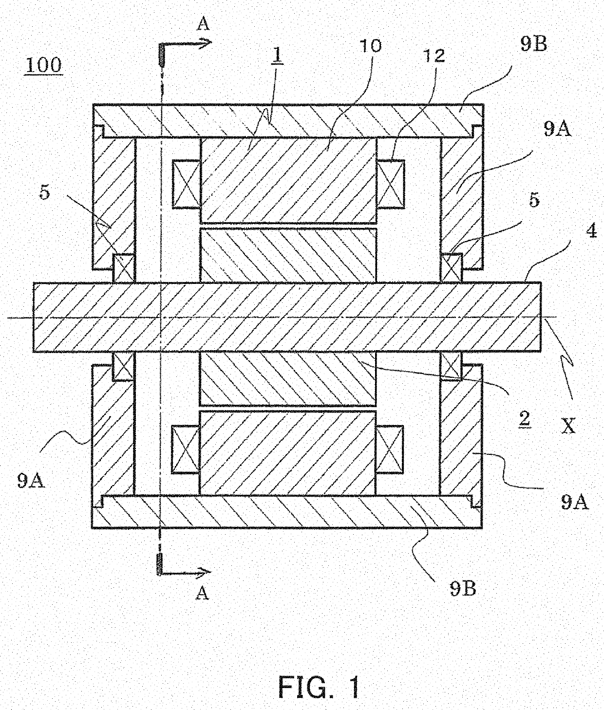
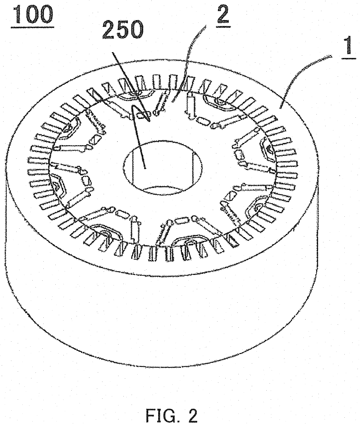
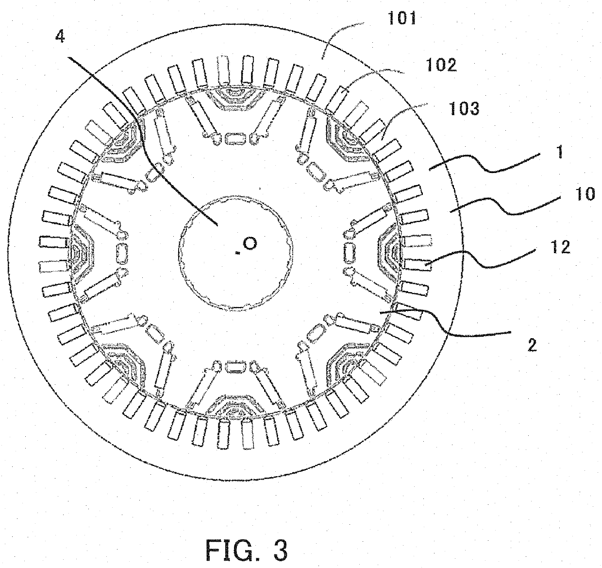
[0036]FIG. 1 is a sectional view for illustrating an overall configuration of a rotating electric machine according to a first embodiment of the present invention. FIG. 2 is a perspective view of the rotating electric machine illustrated in FIG. 1. In FIG. 2, illustration of some components such as housings 9A and 9B and a spindle 4 of FIG. 1 is omitted. FIG. 3 is a sectional view taken along the line A-A of FIG. 1.
[0037]In the first embodiment, a rotating electric machine 100 is described by taking an 8-pole 48-slot three-phase distributed-winding permanent magnet rotating electric machine as an example.
[0038]As illustrated in FIG. 1 to FIG. 3, the rotating electric machine 100 includes a stator 1 and a rotor 2. The stator 1 has an annular shape. The rotor 2 has a columnar shape and is arranged inside the stator 1. An air gap is formed between an inner peripheral surface of the stator 1 and an outer peripheral surface of the rotor 2. Further, as illustrated in FIG. 2, a spindle ins...
second embodiment
[0061]FIG. 9 and FIG. 10 are sectional views of the first rotor unit 201 and the second rotor unit 202 of a rotating electric machine according to a second embodiment of the present invention, respectively. Similarly to FIG. 6 and FIG. 7, FIG. 9 and FIG. 10 are illustrations of one magnetic pole portion of eight magnetic poles of the rotor 2. FIG. 9 is an illustration of a cross section taken along a plane perpendicular to the axial direction of the first rotor unit 201. FIG. 10 is an illustration of a cross section taken along a plane perpendicular to the axial direction of the second rotor unit 202.
[0062]Differences between the first embodiment described above and the second embodiment are described.
[0063]In the first embodiment described above, the slits 22a of the first rotor unit 201 are arranged in three rows, and the slits 22b of the second rotor unit 202 are arranged in two rows. In the second embodiment, however, a slit 22c of the first rotor unit 201 and a slit 22d of the ...
third embodiment
[0077]FIG. 15 and FIG. 16 are sectional views of the first rotor unit 201 and the second rotor unit 202 of a rotating electric machine according to a third embodiment of the present invention, respectively. Similarly to FIG. 6 and FIG. 7, FIG. 15 and FIG. 16 are illustrations of one magnetic pole portion of eight magnetic poles of the rotor 2. FIG. 15 is an illustration of a cross section taken along a plane perpendicular to the axial direction of the first rotor unit 201. FIG. 16 is an illustration of a cross section taken along a plane perpendicular to the axial direction of the second rotor unit 202.
[0078]Differences between the first and second embodiments described above and the third embodiment are described.
[0079]In the first embodiment described above, the angle θm formed between the pair of flux barriers 23a of the first rotor unit 201 and the angle θm formed between the pair of flux barriers of the second rotor unit 202 are the same. In the third embodiment, however, an an...
PUM
 Abstract
Description
Claims
Application Information