Multi-gap type rotary electric machine

a rotary electric machine, multi-gap technology, applied in the direction of dynamo-electric machines, magnetic circuit rotating parts, magnetic circuit shape/form/construction, etc., can solve the problems of increasing magnetic resistance, inability to increase power density, and inability to fully use resistance torque, so as to minimize the effect of magnetic saturation and preventing local demagnetization

Active Publication Date: 2014-06-12
DENSO CORP
View PDF7 Cites 24 Cited by
  • Summary
  • Abstract
  • Description
  • Claims
  • Application Information

AI Technical Summary

Benefits of technology

[0022]Hence it is desired to provide a multi-gap type rotary electric machine which is able to increase the rate of the magnet torque in the outer magnetic circuit and enhance the output torque by providing a configuration in which the reluctance torque is fully used in the inner magnetic circuit.
[0023]There is provided a multi-gap type rotary electric machine which is able to, as another object, prevent demagnetization of magnets, in end portions of each rotor pole, without impairing the performance of the machine and to, as another object, more enhance resistance to demagnetization in the inner magnets than in the outer magnets.
[0032]Further, with the requirements of Formulas (1) and (2) being met, appropriate relationship can be established between P13 (outer-magnet width), P6 (outer-salient-pole width) and P7 (inner-salient-pole width). Accordingly, the rate of the magnet torque is increased in the outer magnetic circuit. In addition, the so rotor yoke, in which the magnetic path is shared between the outer and inner magnetic circuits, is prevented from being magnetically saturated. Thus, the reluctance torque can be fully used in the inner magnetic circuit as well.
[0033]In this way, the multi-gap type rotary electric machine can enhance the output torque, reduce the size and increase the power.
[0035]In the multi-gap type rotary electric machine, the opposite-to-stator surface of either or both of the inner and outer magnets is inclined to gradually reduce the thickness of the magnet in the magnetic pole ends, toward the circumferential ends of the magnet with reference to the circumferentially center portion of the magnet. In other words, the radial width of the rotor yoke, in which a magnetic path common to the inner and outer rotor poles is created, is gradually increased (widened) toward the circumferential ends of each inner or outer rotor pole, with reference to the pole center portion. Thus, in the rotor yoke, magnetic saturation is minimized in the vicinities of the pole end portions. As a result, the occurrence of local demagnetization is prevented in the pole end portions of the magnets.

Problems solved by technology

However, the motor disclosed in the patent document JP-A-2008-302789 suffers from a problem of not being able to increase power density for the reasons set forth below.
Therefore, the reluctance torque cannot be fully used.
Therefore, magnetic resistance is increased and the reluctance torque cannot be fully used.
However, this increases the length of the magnetic path and accordingly increases the magnetic resistance, resulting in decreasing the reluctance torque.
Further, since the increase of the salient-pole width necessarily decrease the magnet width, the magnet torque cannot be fully used as well.
d) Further, due to the increase of the outer-salient-pole width of the rotor, the rotor yoke, in which the magnetic path is shared between the outer and inner magnetic circuits, is unavoidably saturated with the magnetic flux supplied from the outer salient poles to the rotor.
However, the motor disclosed in the patent document JP-A-2007-261342 suffers from problems as set forth below, which should be solved before the motor is put into practical use.
The biggest cause of the above item a) lies in that: magnetic saturation tends to occur in the rotor yoke in which magnetic flux of an inner magnetic circuit and magnetic flux of an outer magnetic circuit join together and flow therethrough and; the magnetic saturation causes magnetic leakage toward the inside of the magnets, resulting in applying a large demagnetizing field to the magnets.
Another cause of bringing local demagnetization is that the tendency of causing magnetic saturation in the salient poles 102 and 103 provided in between the magnetic poles leads to the occurrence of magnetic leakage, resultantly applying a large demagnetizing field to the end portions of each magnetic pole, which are near the salient poles.
However, in a double-stator motor, the increase in the thickness of each magnet leads to the decrease in the thickness of the rotor yoke or the back yoke of either of the inner and outer stators.
As a result, magnetic saturation is caused and the motor performance is impaired.

Method used


Image

  • Multi-gap type rotary electric machine
  • Multi-gap type rotary electric machine
  • Multi-gap type rotary electric machine

Examples


first embodiment

[0059]Referring, first, to FIGS. 1 to 5, hereinafter is described a first embodiment of the present invention.

[0060]In the first embodiment, the multi-gap type rotary electric machine of the present invention is applied to a drive motor 1 which is installed in a vehicle or the like.

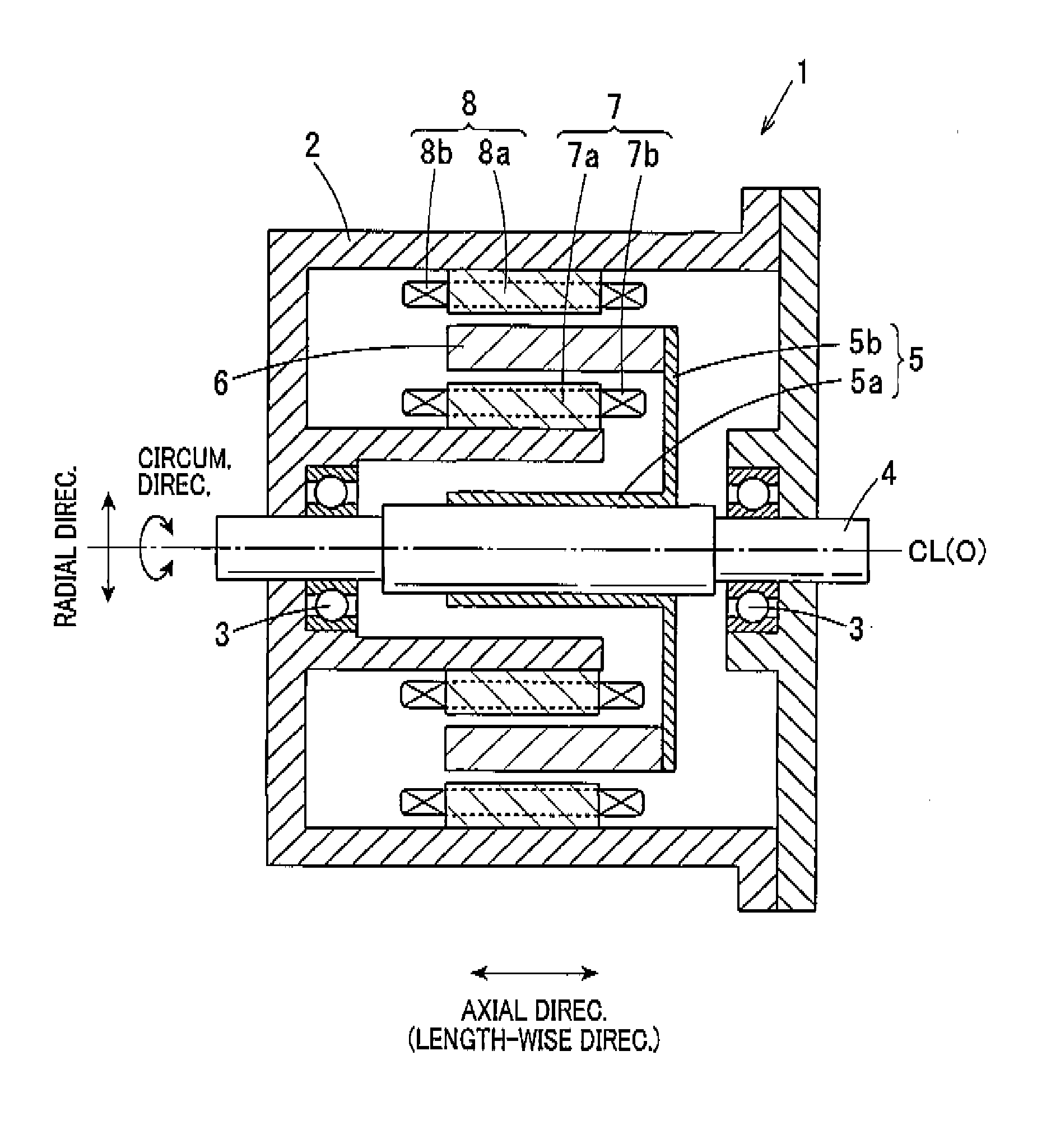
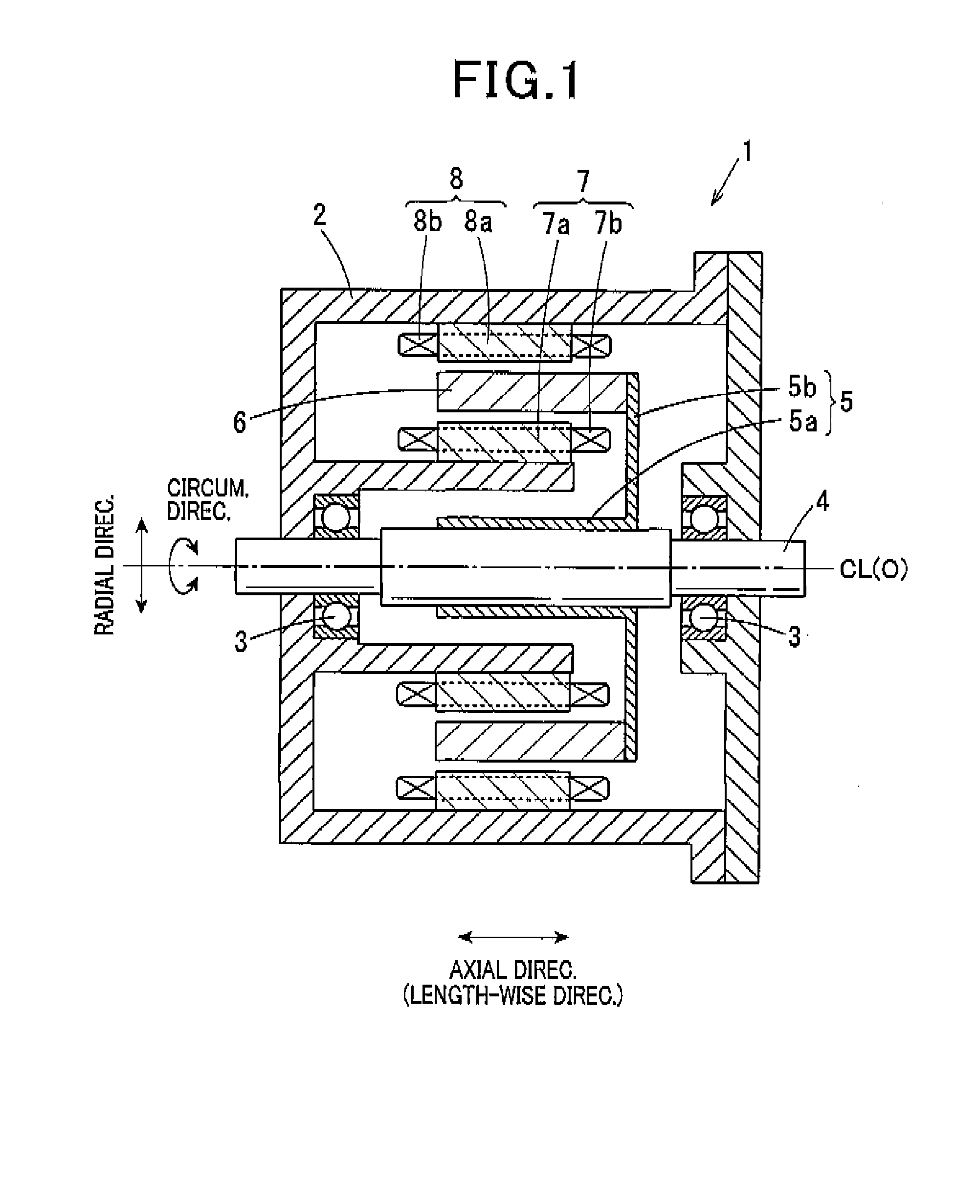
[0061]FIG. 1 is a vertical cross-sectional view illustrating a configuration of the motor 1. As shown in FIG. 1, the motor 1 of the first embodiment includes a motor housing 2, a shaft 4, a rotor 6, an inner stator 7, and an outer stator 8. The shaft 4 is rotatably supported by the motor housing 2 via a baring 3. The rotor 6 is in an annular shape and supported by the shaft 4 via a rotor retaining member 5. The inner stator 7 is arranged radially inside of the rotor 6. The outer stator 8 is arranged radially outside of the rotor 6.

[0062]The shaft 4 is configured to rotate on a length-wise central axis CL passing through a center O in a circular section of the shaft 4, which section is orthogonal to the le...

second embodiment

[0095]In the second embodiment, dimensional ranges at portions related to the magnetic circuits of the motor 1 are set, on condition that the requirements of Formulas (1) and (2) of the first embodiment are met.

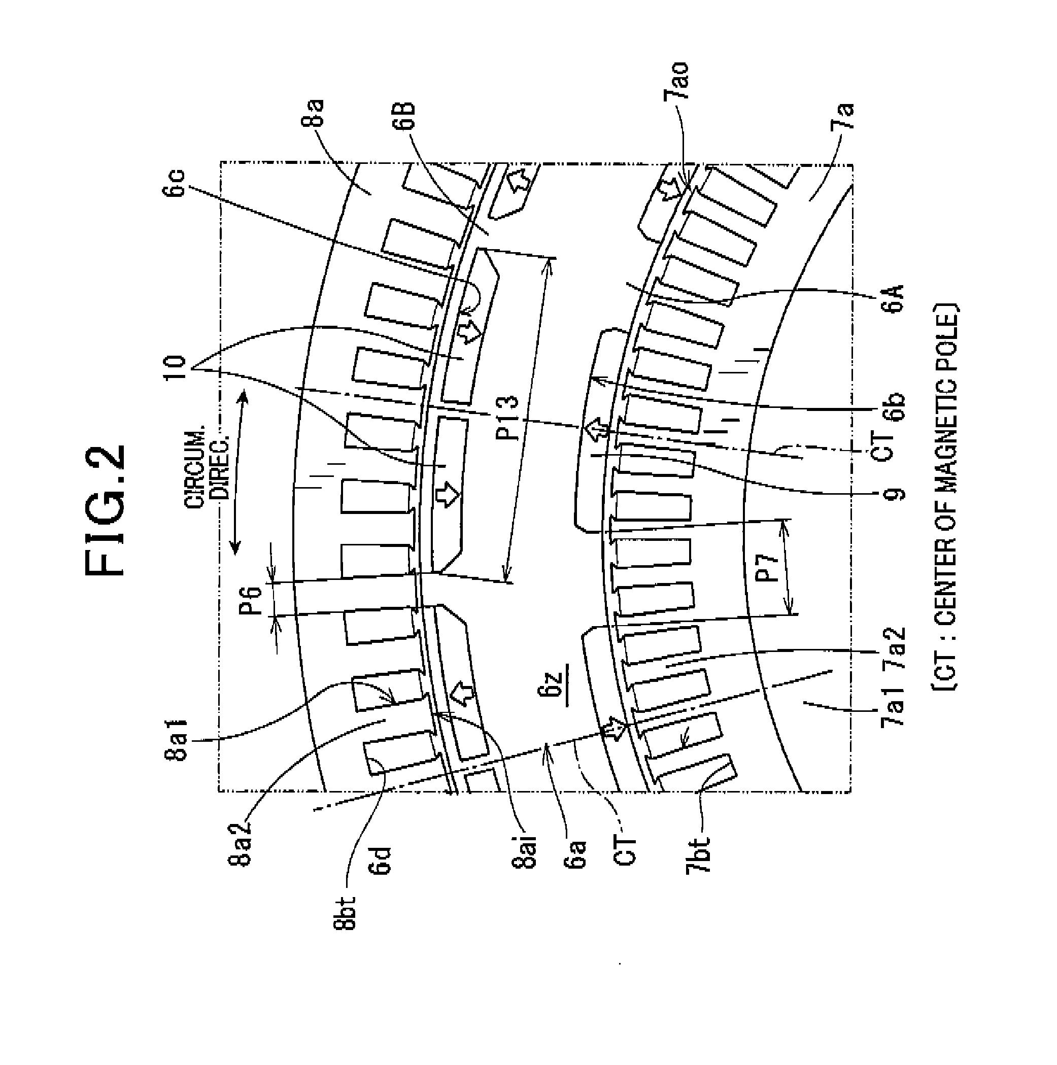
[0096]FIG. 6 is a cross-sectional view illustrating the magnetic circuits of the motor 1 according to the third embodiment. Portions in the magnetic circuits shown in FIG. 6 are denoted as P1 to P13 as follows. It should be appreciated that P6 (outer-salient-pole width), P7 (inner-salient-pole width) and P13 (outer-magnet width) are the same as those of the first embodiment.

[0097]The outer diameter of the outer stator 8 is referred to as outer-stator outer diameter and denoted as P1.

[0098]The diameter of each outer slot 8a1 is referred to as an outer-stator inter-slot diameter and denoted as P2. That is, this diameter P2 is a radial distance between the bottoms of two of the outer slots 8a1, which passes through the central axis CL, that is, the center O, of the shaft 4, as s...

third embodiment

[0114]The third embodiment deals with an example of a triple-gap type motor 1. FIG. 11 is a vertical cross-sectional view illustrating a triple-gap type motor 1 of the fourth embodiment. As shown in FIG. 11, the triple-gap type motor 1 includes a side stator 12 that faces an end face of the rotor 6, which is axially opposite to the rotor disc (on the left in FIG. 11), with a gap therebetween. The side stator 12 includes a side stator core 12a and a side stator winding 12b. The side stator core 12a is connected to the inner and outer stator cores 7a and 8a. A full-pitch winding of the side stator winding 12b is applied to the side stator core 12a. The side stator winding 12b serially connects between the inner and outer stator windings 7b and 8b.

[0115]The triple-gap type motor 1 forms magnetic gaps in three faces between the rotor 6 and the stators 7, 8 and 12. Accordingly, when the requirements of Formulas (1) and (2) of the first embodiment are applied to the magnetic circuits of ...


PUM


Abstract

A multi-gap type rotary electric machine is provided, where the machine is provided a shaft supported rotatably by a baring secured to a housing. An annular rotor is secured to the shaft and configured to rotate together with the shaft. Double stators are secured to the housing and configured to have gaps between the stators and the rotor. Relationships of:3.5<P13 / P6  (1) andP7 / P6>1  (2)are met, where P6 denotes a circumferential width of each of outer salient poles, P7 denotes a circumferential width of each of inner salient poles, and P13 denotes a circumferential width of each of the outer magnets.

Description

CROSS-REFERENCE TO RELATED APPLICATION[0001]This application is based on and claims the benefit of priorities from earlier Japanese Patent Application Nos. 2012-268471 and 2013-223066 filed Dec. 7, 2012 and Oct. 28, 2013, respectively, the descriptions of which are incorporated herein by reference.BACKGROUND OF THE INVENTION[0002]1. Technical Field of the Invention[0003]The present invention relates to a multi-gap type rotary electric machine which is applicable to various uses, such as industrial uses and vehicle uses and in particular is preferred to be used in a drive motor for hybrid vehicles.[0004]2. Related Art[0005]As small and high-power motors based on conventional art, IPM motors (Interior permanent magnet motors) are well known. The IPM motors can use reluctance torque that is a core attractive force, in addition to magnet torque that is generated by magnets. The IPM motors include double-stator motors in which stators are arranged in radially inside and radially outside ...

Claims


Application Information

Patent Timeline
Patent Type & Authority Applications(United States)
IPC IPC(8): H02K1/27H02K3/12
CPCH02K3/12H02K1/276H02K21/12H02K1/27H02K16/04H02K2213/03H02K1/2766H02K1/2706
Inventor KONDOU, KEIJIKUSASE, SHINMAEKAWA, TAKEO
Owner DENSO CORP
Why Eureka
Try Eureka