

Wire Harness Test Device and Method for Verifying Connections when Assembling a Wire Harness
- Summary
- Abstract
- Description
- Claims
- Application Information
AI Technical Summary
Benefits of technology
Problems solved by technology
Method used
Image

Examples
Embodiment Construction
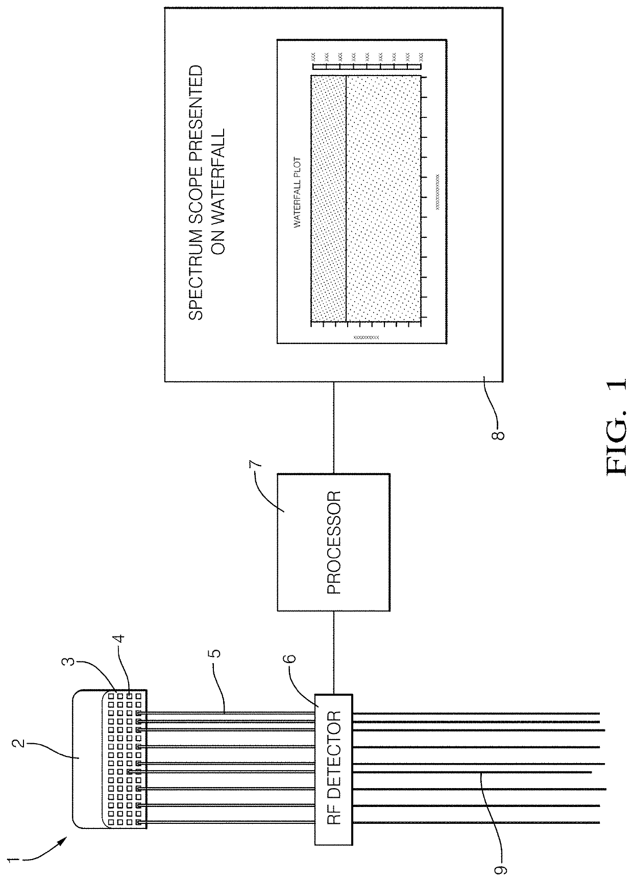
[0025]A schematic diagram of a wiring test device (1) according to an embodiment is shown in FIG. 1. The test device 1 is shown connected to a partially assembled wire harness 9, which comprises a connector housing 3 and a plurality of wires 5. In this illustrative example, the wire harness 9 is shown as a kit type harness, with the proximal ends of the wires 5 connected to individual terminal pins 4 within the terminal array of the connector housing 3, and the distal ends of the wires 5 being free floating. However, it will be understood that one or more of these wires 5 may be terminated with a plug or other connector.
[0026]The connector housing 3 is connected into a corresponding socket provided on the transmitter 2. The socket comprises a plurality of female port terminals which receive the male terminal pins 4 of the connector housing 3 when the connector housing 3 is fitted into the socket. This thereby establishes an electrical connection between the port terminals of the tra...
PUM
 Abstract
Description
Claims
Application Information