
Multi-Coil Wireless Power Transmitter

a wireless power transmitter and multi-coil technology, applied in power conversion systems, battery data exchange, data exchange exchange, etc., can solve problems such as the loss of efficiency of wireless power transmitters, and achieve the effect of efficient power supply

Active Publication Date: 2021-09-09
RENESAS ELECTRONICS AMERICA
View PDF1 Cites 1 Cited by
  • Summary
  • Abstract
  • Description
  • Claims
  • Application Information

AI Technical Summary

Benefits of technology

This patent is about a wireless power transmission system that can efficiently provide power to a receiver based on its position over multiple transmit coils. The system includes a controller that receives position information from sensors and selects the most suitable coils for power transfer based on the receiver's position. The controller also monitors changes in the receiver's position and quickly reassignes the most suitable coils to maintain efficient power transfer. The technical effect of this patent is to provide a more efficient and flexible wireless power transmission system that can adapt to changes in the receiver's position.

Problems solved by technology

However, if the receiver is moved during the wireless power transmission, the wireless power transmitter will lose efficiency.

Method used


Image

  • Multi-Coil Wireless Power Transmitter
  • Multi-Coil Wireless Power Transmitter
  • Multi-Coil Wireless Power Transmitter

Examples


Embodiment Construction

[0015]In the following description, specific details are set forth describing some embodiments of the present invention. It will be apparent, however, to one skilled in the art that some embodiments may be practiced without some or all of these specific details. The specific embodiments disclosed herein are meant to be illustrative but not limiting. One skilled in the art may realize other elements that, although not specifically described here, are within the scope and the spirit of this disclosure.

[0016]This description illustrates inventive aspects and embodiments should not be taken as limiting—the claims define the protected invention. Various changes may be made without departing from the spirit and scope of this description and the claims. In some instances, well-known structures and techniques have not been shown or described in detail in order not to obscure the invention.

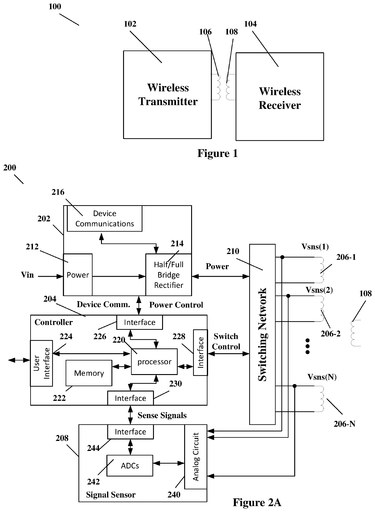
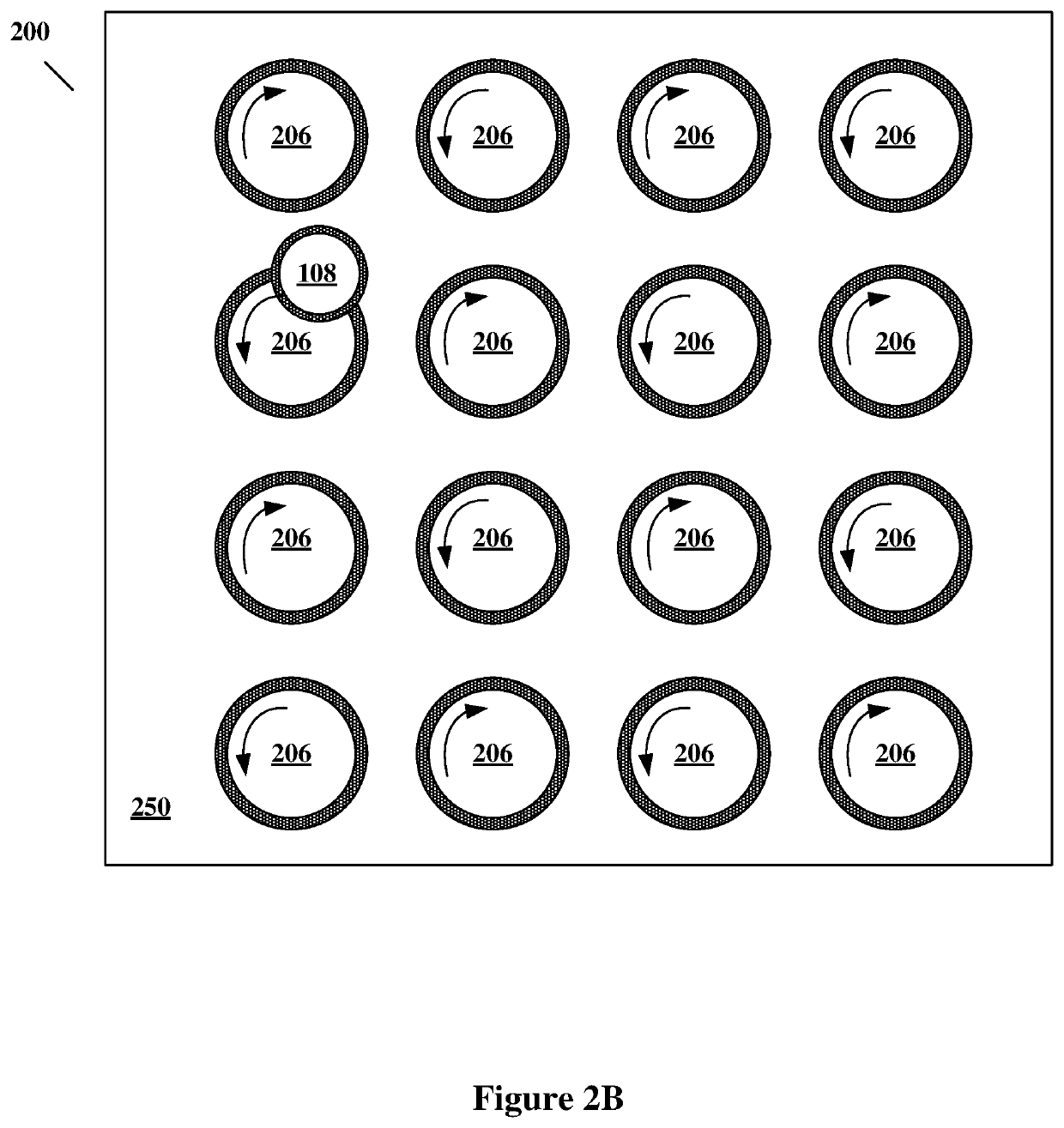
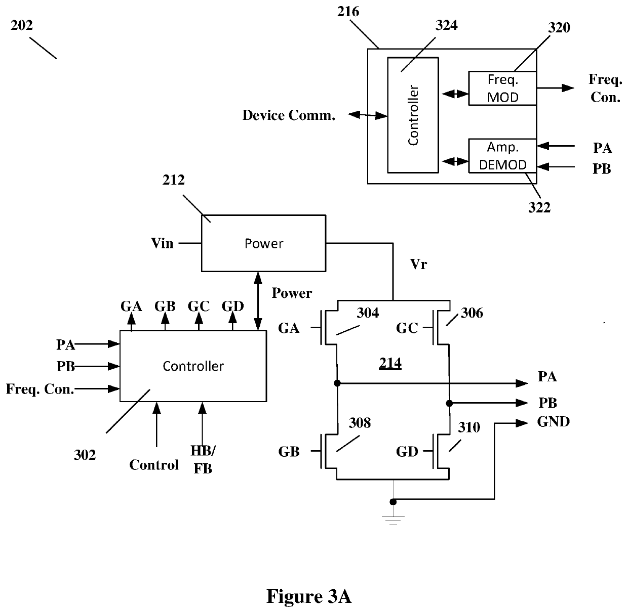
[0017]FIG. 1 illustrates an example wireless power transmission system 100. As illustrated in FIG. 1, a...


PUM


Abstract

A system and method of transmitting power according to some embodiments includes sequentially pinging each of a plurality of transmit coils to locate a receiver; determining one or more active coils from the plurality of transmit coils based on the location of the receiver; activating the one or more active coils in a full-bridge mode to transfer power to the receiver; determining a base efficiency based on the one or more active coils; monitoring non-active ones of the plurality of transmit coils; determining if the receiver has moved based on the monitoring; if the receiver has moved to a new position, determining secondary coils according to the new position, and transitioning power to provide power from a new active coil configuration.

Description

TECHNICAL FIELD[0001]Embodiments of the present invention are related to wireless transmission of power and, in particular, to operating a multi-coil wireless power transmitter in the presence of a wireless power receiver.DISCUSSION OF RELATED ART[0002]Mobile devices, for example smart phones, tablets, wearables and other devices are increasingly using wireless power charging systems. In general, wireless power transfer involves a transmitter driving a transmit coil and a receiver with a receiver coil placed proximate to the transmit coil. The receiver coil receives the wireless power generated by the transmit coil and uses that received power to drive a load, for example to provide power to a battery charger.[0003]There are multiple different standards currently in use for the wireless transfer of power. The most common standard for wireless transmission of power is the Wireless Power Consortium standard, the Qi Standard. Under the Wireless Power Consortium, the Qi specification, a...

Claims


Application Information

Patent Timeline
Patent Type & Authority Applications(United States)
IPC IPC(8): H02J50/40H02J50/80H02J50/12
CPCH02J50/402H02J50/12H02J50/80H02J50/90H02J50/40H02J50/10H02J7/02H02M7/219H02J7/00034
Inventor SMITH, NICHOLAUS
Owner RENESAS ELECTRONICS AMERICA
Learn More