
Power supply for 2-line dimmer

a power supply and dimmer technology, applied in the direction of electric variable regulation, process and machine control, instruments, etc., can solve the problems of high implementation cost, bulky components and inefficiency, and power supply cores which are much smaller and lighter

Inactive Publication Date: 2007-06-07
LEVITON MFG
View PDF12 Cites 19 Cited by
  • Summary
  • Abstract
  • Description
  • Claims
  • Application Information

AI Technical Summary

Benefits of technology

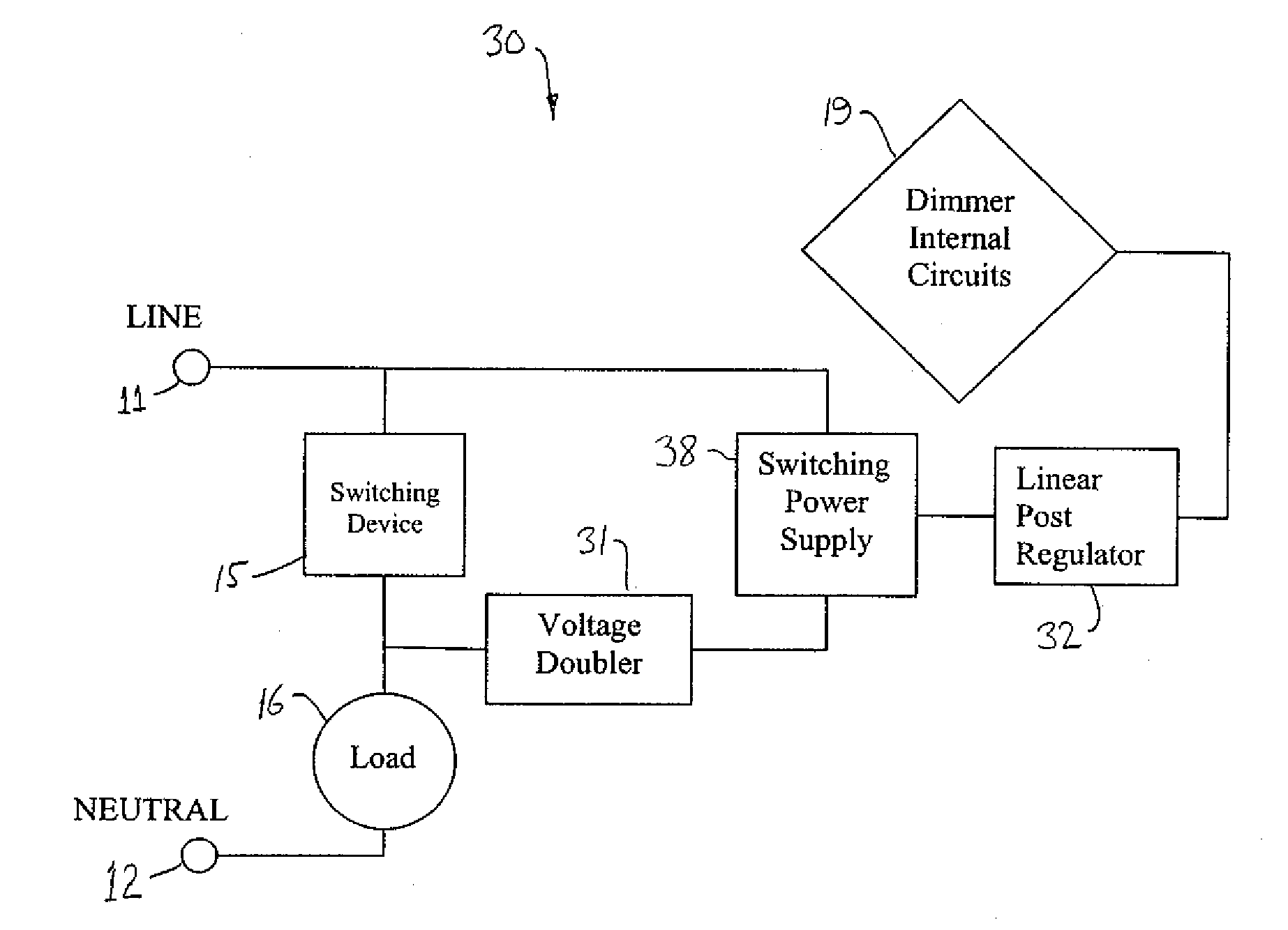
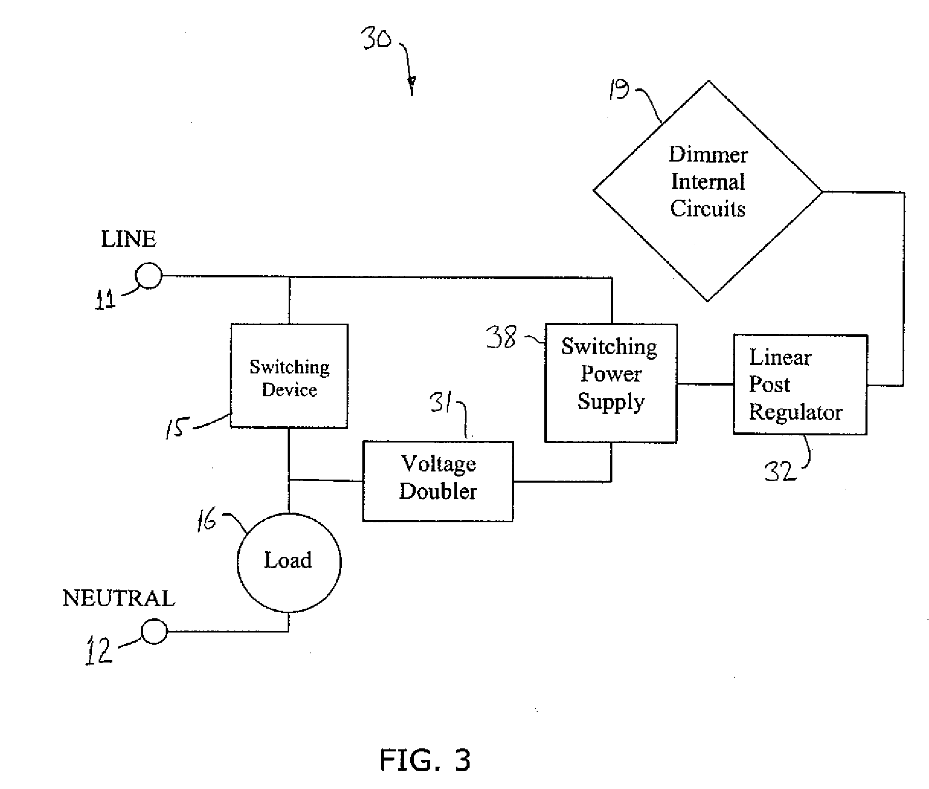
[0009] The present invention addresses the above-noted problems by providing a switching power supply circuit in which the input voltage level is increased, thereby improving the performance of the switching power supply. A voltage multiplier such as a voltage doubler circuit is introduced between the load switching device and the input to the switching power supply. The voltage multiplier permits stable operation of the power supply even at low voltages.
[0011] According to another aspect of the invention, a power supply circuit for connection to a lighting dimmer device is provided which includes a voltage doubler circuit, a filter circuit, a switching power supply, and a linear regulator circuit In one embodiment, the voltage doubler circuit includes a first stage having a first capacitor and a first diode, and a second stage having a second capacitor and a second diode. The switching power supply may include a feedback circuit, and may be a non-isolated power supply. In an embodiment, the dimmer device is variable between an OFF position and a full ON position, and the circuit is effective to provide power for operation of the switching power supply while the dimmer device is in the full ON position.

Problems solved by technology

These designs have a number of drawbacks, including bulky components and inefficiency, as they can draw current while the device is in its OFF state.
These power supplies also sometimes have high implementation costs.
This results in a core which is much smaller and lighter compared to a conventional power supply.
Furthermore, a linear regulator can neither boost nor switch polarity.
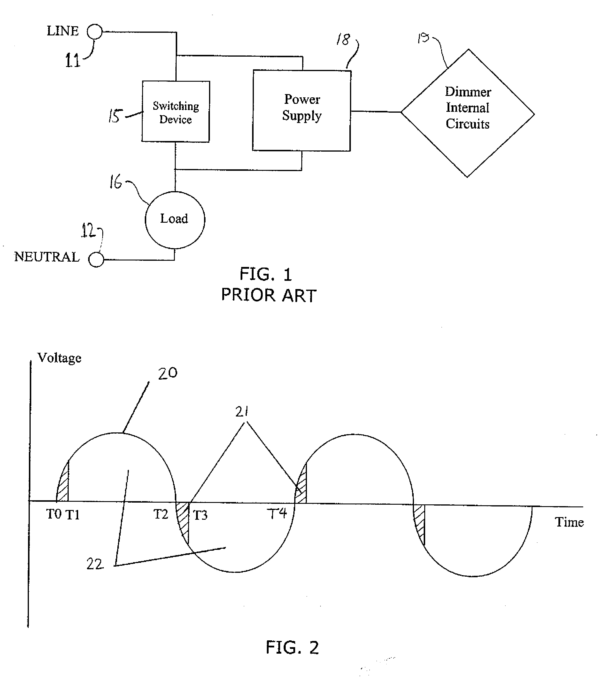
The design of this type of power supply can be a problem because the available AC power source will normally depend on the status of the load.
As shown in FIG. 2, when the AC input power can be utilized only during short intervals of time around the zero crossing, peak voltage levels which develop while the load is OFF can be marginal for switching operation or may not provide enough energy for the required power output.
Switching power supplies therefore may not be suitable for use in lighting applications, which normally require unobstructed line access and input voltage values which are not too low for the switching power supply to operate properly.
A similar problem may arise in home energy management systems, in which the power switching device is placed in series with a 24V or 120V power source and a load (as discussed in U.S. Pat. No. 4,678,985).

Method used


Image

  • Power supply for 2-line dimmer
  • Power supply for 2-line dimmer
  • Power supply for 2-line dimmer

Examples


Embodiment Construction

[0016]FIG. 3 shows a block diagram of a switching power supply 30 according to an embodiment of the invention. In this embodiment, a voltage multiplier such as a voltage doubler is used to increase the input voltage level of the power supply, thereby assuring proper operation of the power supply even when the dimmer is at its full ON position. A voltage doubler circuit 31 is connected between the switching device 15 and the input to the switching power supply 38. This arrangement permits direct access to the line terminal 11 for various components of the dimmer providing other optional dimmer functions such as communication to remote devices. Other voltage multiplication circuits besides voltage doublers (e.g. 3×) may also be used. A linear post regulator 32 may be advantageously placed between the output of power supply 38 and the dimmer internal circuits 19. Noise sensitive dimmer circuits may particularly benefit from an additional linear post regulator.

[0017] Referring to FIG. ...


PUM


Abstract

A power supply circuit for a dimmer switching device includes a voltage doubler circuit, a filter circuit, a switching power supply, and a linear regulator circuit. In one embodiment, the voltage doubler circuit includes a first stage having a first capacitor and a first diode, and a second stage having a second capacitor and a second diode. The switching power supply may include a feedback circuit, and may be a non-isolated power supply. In an embodiment, the dimmer device is variable between an OFF position and a full ON position, and the circuit is effective to provide power for operation of the switching power supply while the dimmer device is in the full ON position.

Description

[0001] This application claims the benefit of U.S. Provisional Application No. 60 / 730,981, filed Oct. 27, 2005.FIELD OF THE INVENTION [0002] The present invention relates generally to power supplies utilized in lighting control applications and, more specifically, to power supplies used to power internal dimmer circuits. BACKGROUND OF THE INVENTION [0003] A common application for a two wire connection circuit is to power the internal control of a dimmer. Conventional power supplies for two line dimmers are often based on a linear analog approach, including different capacitor charging schemes with a linear post regulator. Examples of power supplies utilizing this approach are shown in U.S. Pat. Nos. 4,334,184; 4,504,778; 4,678,985; and 5,600,552. These designs have a number of drawbacks, including bulky components and inefficiency, as they can draw current while the device is in its OFF state. These power supplies also sometimes have high implementation costs. [0004] A switching pow...

Claims


Application Information

Patent Timeline
Patent Type & Authority Applications(United States)
IPC IPC(8): H05B39/04
CPCH02M7/217H02M2001/0006H02M2001/007H05B39/04Y10S315/04H02M1/0006H02M1/007
Inventor FRID, EUGENE
Owner LEVITON MFG
Learn More