
Rotary sensor assembly with low-power feature

a sensor and low-power technology, applied in the field of rotary sensor assembly with low-power feature, can solve the problems of misleading basis, inability to easily upload log information to a computer for data processing, and most devices of today are withou

Active Publication Date: 2021-08-10
NOVO NORDISK AS
View PDF21 Cites 1 Cited by
  • Summary
  • Abstract
  • Description
  • Claims
  • Application Information

AI Technical Summary

Benefits of technology

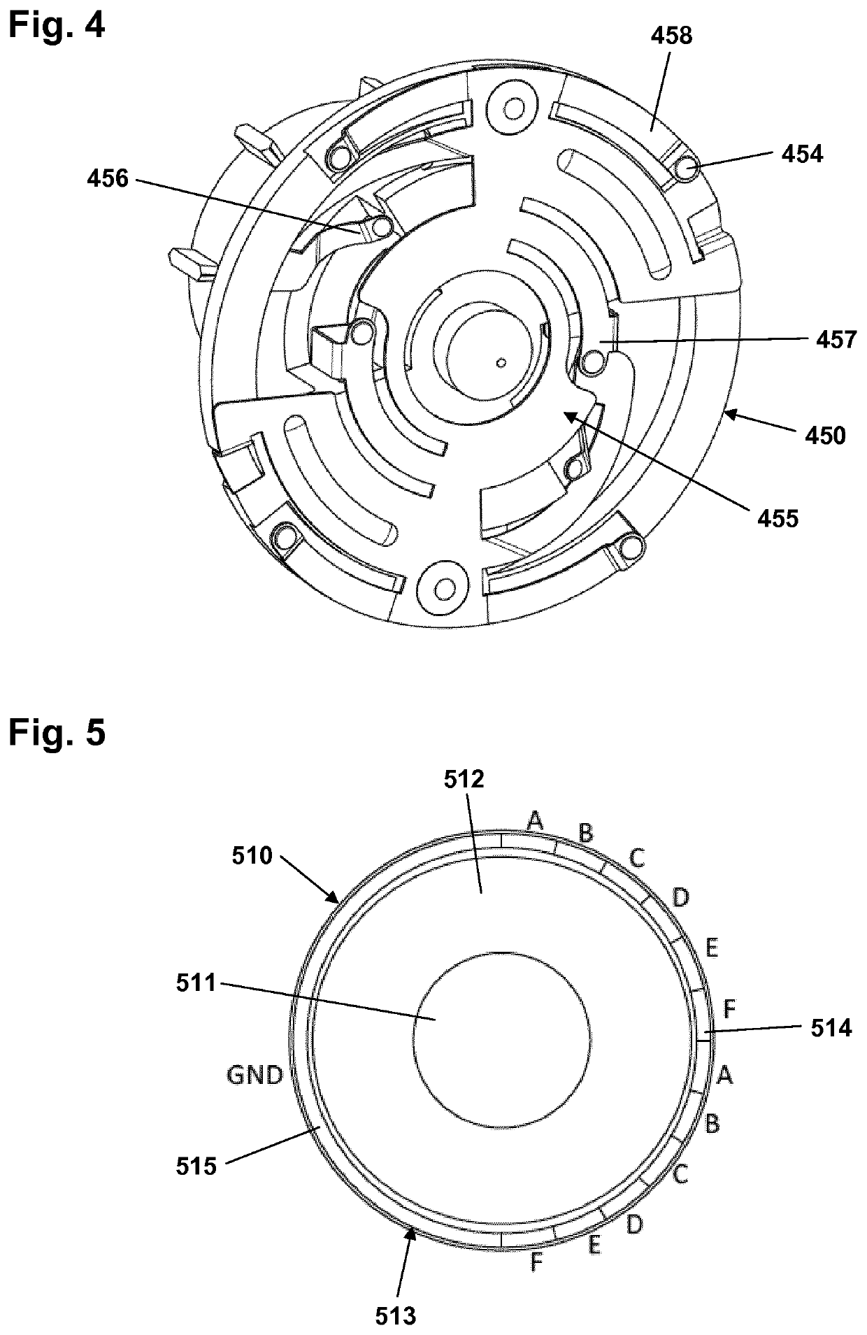
The patent describes a way to make a rotational encoder that can detect changes in position with very high resolution. This is done by using active circuitry to manage power, which means the system can detect changes in a single index at any given position. This arrangement also allows the encoder to power up from a low-power sleep mode to a high-power operational state without needing an extra track for wakeup, which makes the sensor more compact. Grounding and coding can be combined in a single pattern, which makes the design more compact. The resolution will be lower when half the circumference is used for a ground track, but the system can still detect changes in position accurately.

Problems solved by technology

However, such logs are normally kept in handwritten notebooks, from the logged information may not be easily uploaded to a computer for data processing.
A missing or erroneous record in the log results in a misleading picture of the injection history and thus a misleading basis for the medical personnel's decision making with respect to future medication.
However, most devices of today are without it.

Method used


Image

  • Rotary sensor assembly with low-power feature
  • Rotary sensor assembly with low-power feature
  • Rotary sensor assembly with low-power feature

Examples


Embodiment Construction

[0038]When in the following terms such as “upper” and “lower”, “right” and “left”, “horizontal” and “vertical” or similar relative expressions are used, these only refer to the appended figures and not necessarily to an actual situation of use. The shown figures are schematic representations for which reason the configuration of the different structures as well as their relative dimensions are intended to serve illustrative purposes only. When the term member or element is used for a given component it generally indicates that in the described embodiment the component is a unitary component. However, the same member or element may alternatively comprise a number of sub-components just as two or more of the described components could be provided as unitary components, e.g. manufactured as a single injection moulded part. The terms “assembly” and “subassembly” do not imply that the described components necessarily can be assembled to provide a unitary or functional assembly or subasse...


PUM


Abstract

A rotary sensor assembly, comprising a first sensor part with a plurality of position sensor segments, and a second sensor part with a grounded contact in contact with a position sensor segment. For a current incremental rotational position a contact is in contact with an un-powered current-position sensor segment, with the neighbour segments being in a powered state. When the contact is rotated to a powered next-position position sensor segment, the next-position sensor segment becomes a new current-position sensor segment. Electronic circuitry is adapted to detect that the new current-position sensor segment is grounded and that the first and second sensor parts thereby have been rotated one increment relative to each other, and subsequently change the state of the former current-position sensor segment from un-powered to powered and the state of the new current-position sensor segment from powered to un-powered.

Description

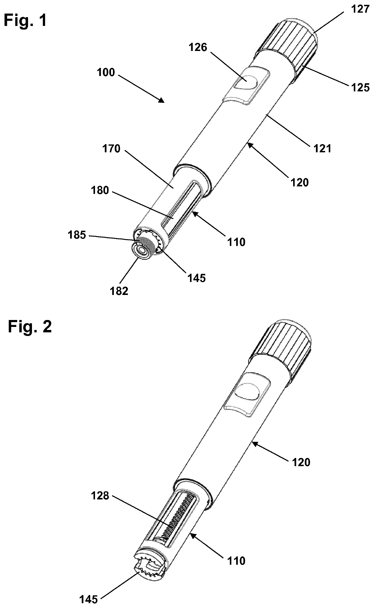
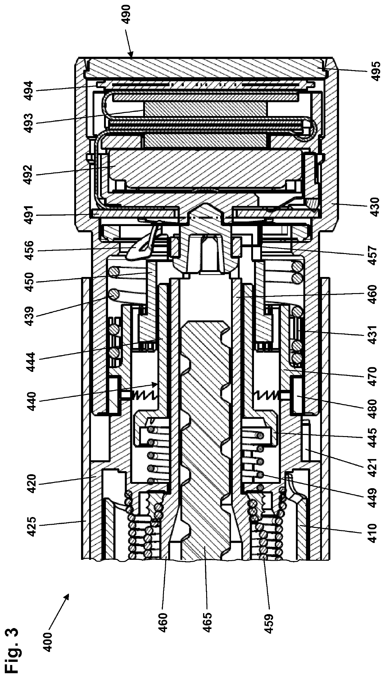
CROSS-REFERENCE TO RELATED APPLICATIONS[0001]This application is a 35 U.S.C. § 371 National Stage application of International Application PCT / EP2016 / 082513 (published as WO 2017 / 114768), filed Dec. 23, 2016, which claims priority to European Patent Application 15202797.5, filed Dec. 28, 2015, the contents thereof which are incorporated by reference in their entirety.Rotary Sensor Assembly with Low-Power Feature[0002]The present invention relates to assemblies, devices and systems adapted for capturing information in respect of rotational movement. The invention provides assemblies, devices and systems which are relevant in applications in which energy- and space-efficient design are of importance. In a specific aspect the invention addresses issues relating to electronic dose data capturing in and for a drug delivery device.BACKGROUND OF THE INVENTION[0003]Rotary sensor assemblies are used in numerous applications in numerous technical fields. In the disclosure of the present inven...

Claims


Application Information

Patent Timeline
Patent Type & Authority Patents(United States)
IPC IPC(8): A61M5/315G01D5/252A61M5/31
CPCA61M5/31553A61M5/31568A61M5/31593G01D5/252A61M2005/3126A61M2205/52A61M5/20A61M5/24
Inventor GRUBBE, MIKKEL SCHOUENBORG
Owner NOVO NORDISK AS
Learn More