

Duplex optical connector plug
- Summary
- Abstract
- Description
- Claims
- Application Information
AI Technical Summary
Benefits of technology
Problems solved by technology
Method used
Image

Examples
Embodiment Construction
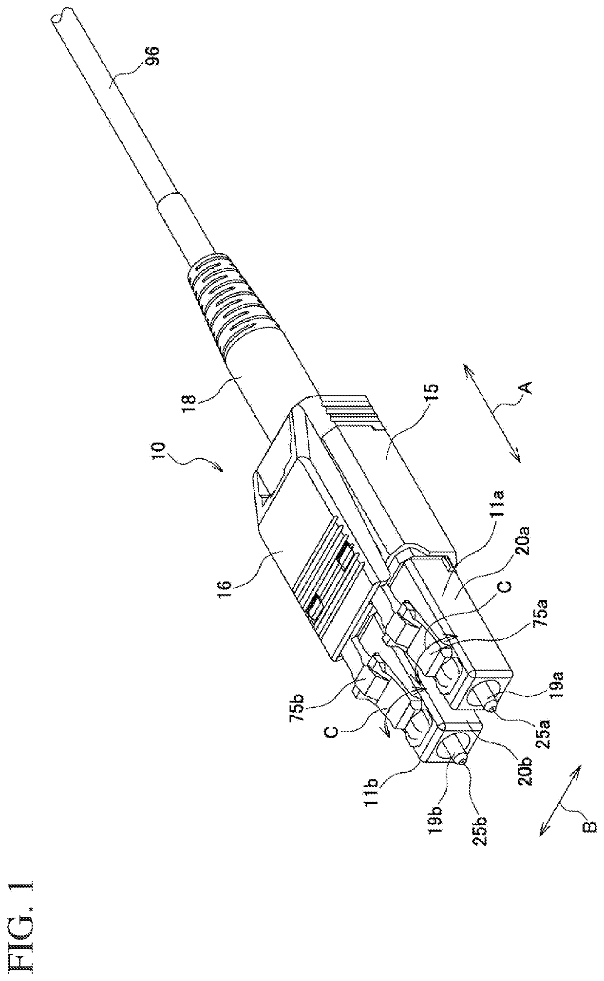
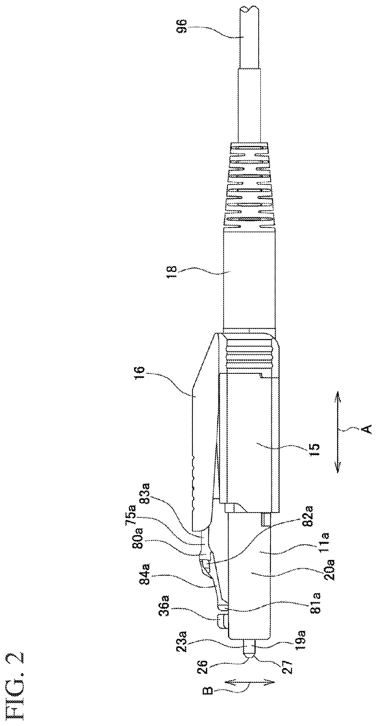
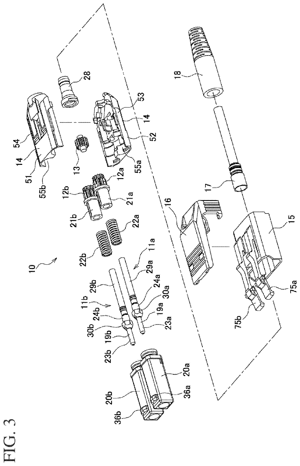
[0045]Hereinafter, with reference to the drawings, a description will be given of a duplex optical connector plug 10 according to an embodiment. FIG. 1 is a perspective view of a duplex optical connector plug 10 according to an embodiment. FIG. 2 is a side view of the duplex optical connector plug 10. FIG. 3 is an exploded perspective view of the duplex optical connector plug 10. FIG. 4 is a perspective view of the first and second plug frames 20a, 20b. FIG. 5 is a cross-sectional view taken along line A-A in FIG. 4. FIG. 6 is a perspective view of first and second stop rings 21a, 21b. In FIGS. 1 and 2, the axial direction is indicated by arrow A; the radial direction (the lateral direction or the vertical direction) is indicated by arrow B; and the circumferential direction is indicated by arrow C.
[0046]The duplex optical connector plug 10 is mounted on a terminal part of an optical fiber cord 96 and connected to an optical connector adaptor (not illustrated) for establishing an op...
PUM
 Abstract
Description
Claims
Application Information