Counter-Balanced Lift System

a counterbalanced and lift technology, applied in the field of counterbalanced lift systems, can solve the problems of counterbalance for the weight of the door, prolonging the storage of the counterbalance system, and the torque shaft extending the full width of the door, so as to achieve the effect of offset the weight of the lift door

Pending Publication Date: 2021-09-23
WAIT DOUGLAS
View PDF9 Cites 0 Cited by
  • Summary
  • Abstract
  • Description
  • Claims
  • Application Information

AI Technical Summary

Benefits of technology

[0007]A counterbalance mechanism for a lift door system is described herein, in embodiments, the counterbalance mechanism comprising an adjustable length torque shaft positionable above a lift door, wherein length of the torque shaft is selected to extend at least proximate to a width of the lift door. The mechanism also includes two cable drums mounted proximate to opposite ends of the adjustable length torque shaft for rotation with the torque shaft, the cable drums supporting flexible cables that connect to the lift door to support at least a portion of weight of the lift door. In addition, the counterbalance mechanism includes two torsion springs disposed around the adjustable length shaft and operably connected to the adjustable length torque shaft, wherein the two torsion springs exert a torsional force on the adjustable length torque shaft to counterbalance at least a portion of the weight of the lift door and assist in movement of the lift door, where each of the torsion springs are anchored to a mounting bracket.
[0008]Methods of installation for a counterbalance mechanism are described, including a method of installing a counterbalance mechanism for a lift door, comprising lifting an adjustable length torque shaft into a first and second mounting bracket, wherein the first and second mounting bracket are positioned above the lift door and at opposite sides of the lift door. In embodiments, the adjustable length torque shaft comprises a first outer torque shaft and a second outer torque shaft connected via a middle torque shaft, as well as a first and second torsion spring. The first torsion spring attached to the first outer torque shaft so that the first torsion spring is rotationally fixed to the first outer torque shaft and the second torsion spring attached to the second outer torque shaft so that the second torsion spring is rotationally fixed to the second outer torque shaft. The adjustable length shaft also includes a first cable drum attached to the first outer torque shaft and a second cable drum attached to the second outer torque shaft. The method of installation includes connecting the second end of the first torsion spring to the first mounting bracket, connecting the second end of the second torsion spring to the second mounting bracket, attaching a cable to each of the cable drums with the other end of the cable attached to the lift door, and adjusting tension on the first and second torsion springs to offset weight of the lift door.

Problems solved by technology

As the shaft rotates, during raising and lowering of the door, the torsion of the spring provides a counterbalance for the weight of the door.
One problem with these conventional lift systems is that the torque shaft extends the full width of the door on which it is installed.
This can result in prolonged storage of the counterbalance systems, taking up significant floor space with unsold systems.
This makeshift solution introduces two complications.
The first complication is shipping cost.
Due to the length, the shipping containers are not standard, and, thus, the shipping of traditional counterbalance lift systems is expensive.
The second complication is that the end consumer must alter the torque shaft to fit the desired fixed length.
This requires expertise, time and expensive equipment that the consumer may not have.

Method used


Image

  • Counter-Balanced Lift System
  • Counter-Balanced Lift System
  • Counter-Balanced Lift System

Examples


Embodiment Construction

[0027]Aspects of the system and methods are described below with reference to illustrative embodiments. The references to illustrative embodiments below are not made to limit the scope of the claimed subject matter. Instead, illustrative embodiments are used to aid in the description of various aspects of the systems and methods. This description, made by way of example and reference to illustrative reference, is not meant to be limiting as regards any aspect of the claimed subject matter.

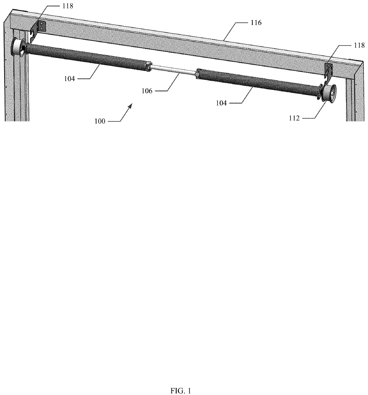
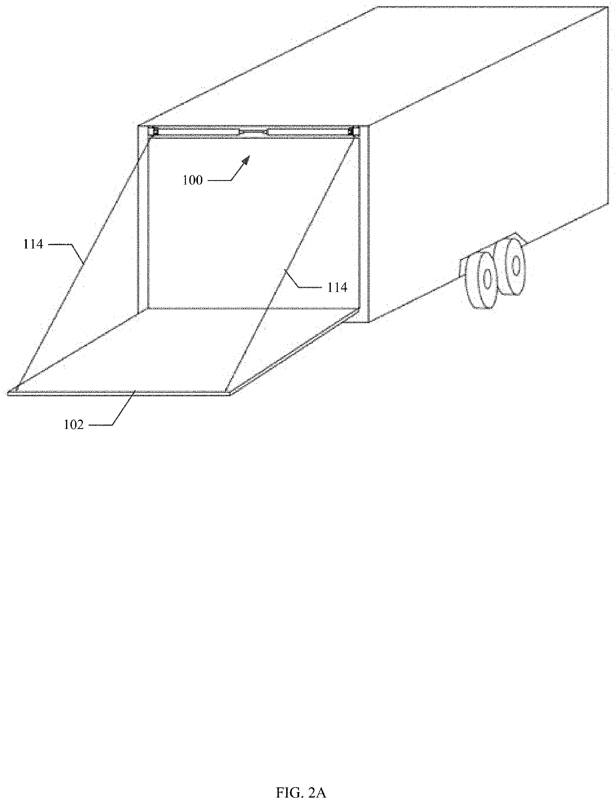
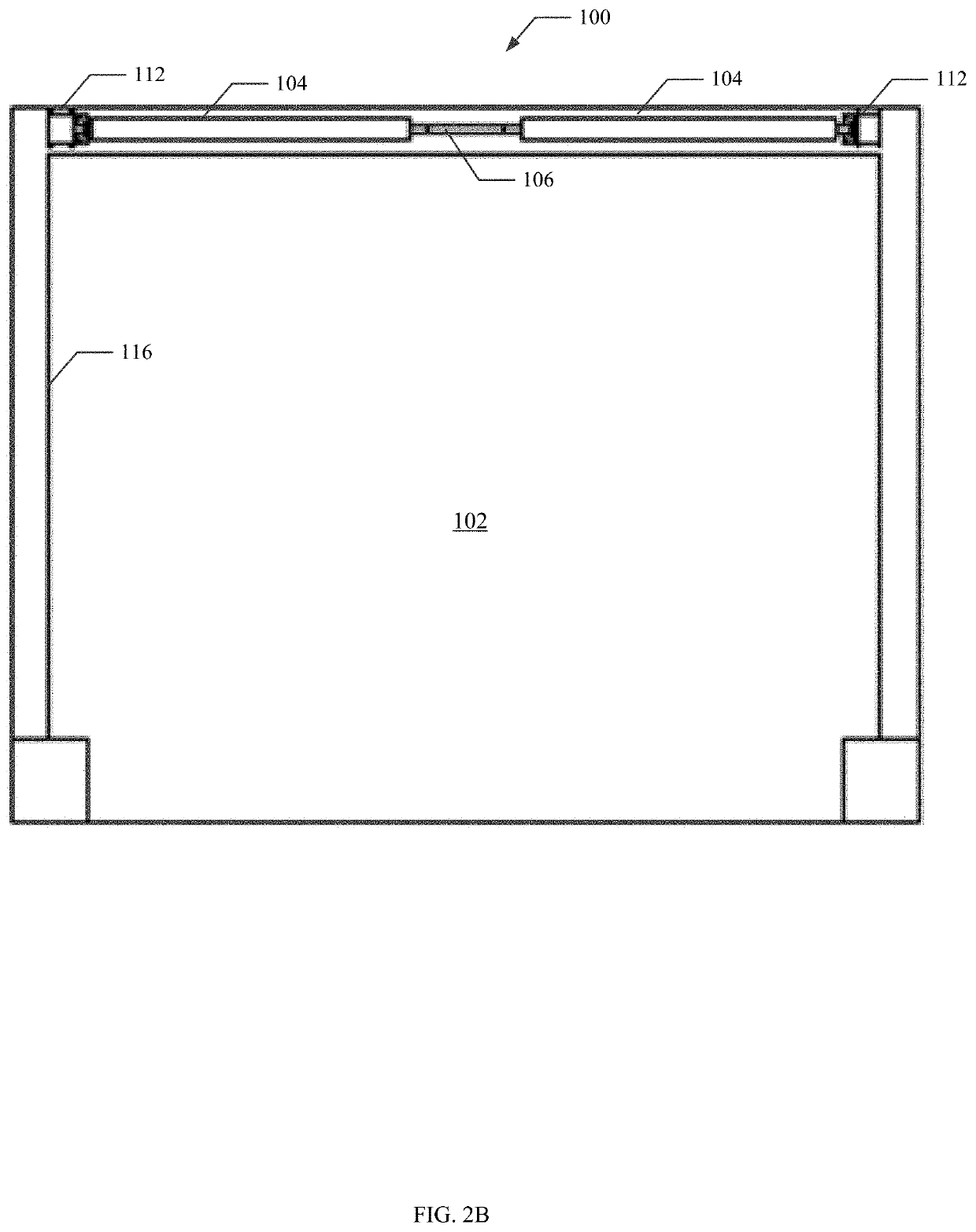
[0028]Turning to FIG. 1, an embodiment of a counterbalance mechanism 100 for use with a lift door 102 is illustrated. Conventionally, counterbalance mechanisms 100 (also referred to herein as “counterbalance systems” or “lift systems”) are mounted directly above the lift door 102 to which they are attached. Lift doors 102 are commonly used for cargo trailers, garage doors and numerous other applications as the door is conveniently lifted up and out of the way to open the doorway. In a typical lift ...


PUM


Abstract

An adjustable length counterbalance mechanism for lift doors, frequently used for cargo trailers and garages. The adjustable length torque shaft of the counterbalance mechanism is able to accommodate many different lift door widths and is simpler to install than a fixed length torque shaft. In embodiments, the adjustable torque shaft is comprised of two outer torque shafts, each with a torsion spring and cable drum and a middle torque shaft that can be assembled together. The middle torque shaft can be inserted into each of the outer torque shafts to a selected depth to determine the length of the adjustable torque shaft.

Description

CROSS-REFERENCE TO RELATED APPLICATIONS[0001]This application claims benefit of the filing date U.S. Provisional Patent Application No. 62 / 991,293 entitled Counter-Balanced Lift System, filed on Mar. 18, 2020, which is herein incorporated by reference in its entirely.BACKGROUND[0002]Generally, overhead lift doors provide convenient and effective means for closing off large entrances including, but not limited to, garage doors and cargo trailers. Accordingly, lift doors are common in buildings, trucks and other transportation and storage facilities. There are a variety of lift doors including, but not limited to, ramp doors and roll-up doors, including multi-panel roll doors.[0003]Conventional lift systems use springs to counterbalance the weight of the door, making the opening and closing of the lift door easier, safer, and more reliable. Cables are spooled around cable drums attached to each end of a torque shaft. The other ends of the cables are attached to each side the door, suc...

Claims


Application Information

Patent Timeline
Patent Type & Authority Applications(United States)
IPC IPC(8): E05D13/00
CPCE05D13/1253B60J5/108E05Y2201/672E05Y2900/106E05Y2900/516E05Y2201/706E05Y2600/10E05Y2800/205
Inventor WAIT, DOUGLAS
Owner WAIT DOUGLAS
Why Eureka
Try Eureka