Relay state determination device, relay state determination system, relay state determination method, and non-transitory computer readable medium

Pending Publication Date: 2021-09-23
ORMON CORPORATION
View PDF0 Cites 0 Cited by
  • Summary
  • Abstract
  • Description
  • Claims
  • Application Information

AI Technical Summary

Benefits of technology

The patent is about a device, system, method, and program that can determine if a relay is working properly. The technical effect is to allow for individual pole detection and timely replacement to prevent malfunctions.

Problems solved by technology

However, Patent Document 1 (JP 2013-89603 A) has a problem that, if the relay is a multipole type, deterioration of each individual pole is difficult to be determined.

Method used


Image

  • Relay state determination device, relay state determination system, relay state determination method, and non-transitory computer readable medium
  • Relay state determination device, relay state determination system, relay state determination method, and non-transitory computer readable medium
  • Relay state determination device, relay state determination system, relay state determination method, and non-transitory computer readable medium

Examples


Embodiment Construction

[0041]Hereinafter, an embodiment of the present disclosure is described in detail with reference to the drawings.

[0042](Schematic Configuration of Relay State Determination System 100)

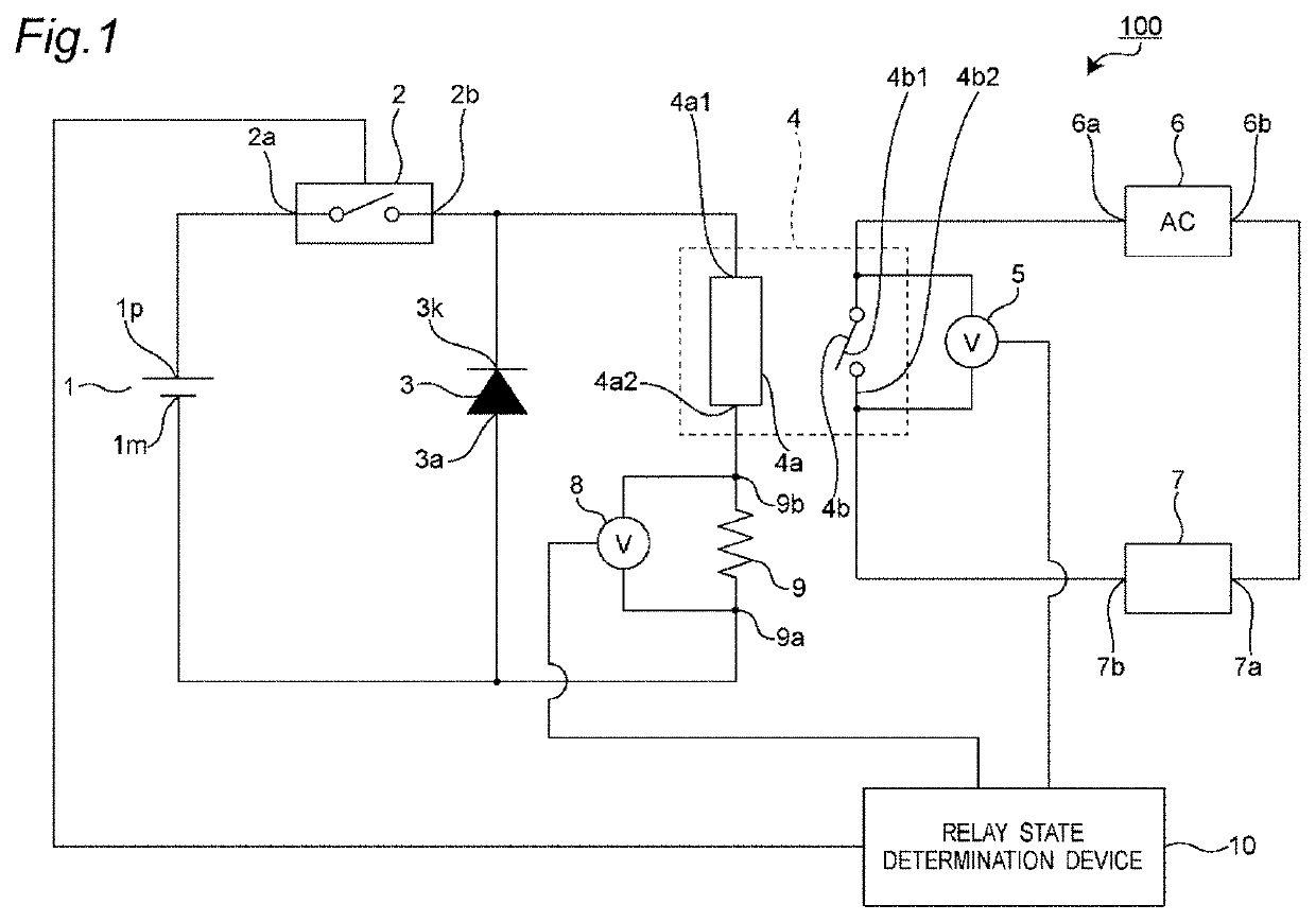
[0043]FIG. 1 shows an overall configuration of a relay state determination system 100. As an example, the relay state determination system 100 determines whether or not a relay 4 has deteriorated. Here, “deterioration” of the relay 4 means that opening and closing of the relay 4 may not be normally operated. In other words, failure may have occurred. This is a state of the relay 4.

[0044]As shown in FIG. 1, the relay state determination system 100 includes the relay 4, voltmeters 5 and 8, and a relay state determination device 10. The relay state determination system 100 further includes a direct current (DC) power supply 1, a switch device 2, a diode 3, a shunt resistor 9, an alternating current (AC) power supply 6, and a load 7.

[0045]As shown in FIG. 1, the relay 4 is arranged across a primary-side ci...


PUM


Abstract

A relay state determination device according to the present invention includes: a voltage value acquisition unit that measures every moment a detected voltage detected from two ends of a shunt resistor; a voltage value difference calculation unit that calculates a voltage value difference between a first voltage value of when the detected voltage becomes minimum by an armature starting displacement after a primary-side switch is turned off and a second voltage value of when secondary-side contacts are opened; and a state determination unit that determines that a relay has deteriorated when the voltage value difference falls below a predetermined threshold value.

Description

CROSS-REFERENCE TO RELATED APPLICATION[0001]This is a continuation application of International Application No. PCT / JP2019 / 045184, with an International filing date of Nov. 19, 2019, which claims priority of Japanese Patent Application No. 2018-237585 filed on Dec. 19, 2018, the entire content of which is hereby incorporated by reference.TECHNICAL FIELD[0002]The present invention relates to a relay state determination device, a relay state determination system, a relay state determination method, and a non-transitory computer readable medium, and relates to, for example, a relay state determination device, a relay state determination system, a relay state determination method, and a non-transitory computer readable medium which can determine whether or not there is deterioration in a relay of a type that opens and closes a contact on a secondary side by turning on and off energization to a coil on a primary side.BACKGROUND ART[0003]Conventionally, as this type of relay state determi...

Claims


Application Information

Patent Timeline
IPC IPC(8): G01R31/327H01H47/00H01H50/54H01H50/18
CPCG01R31/3278H01H50/18H01H50/54H01H47/002H01H1/0015H01H2071/044
Inventor MATSUO, SHINYAYAMAZAKI, TAKUYA
Owner ORMON CORPORATION
Why Eureka
Try Eureka