Method for improving fatigue resistance performance of locomotive rubber-metal pad with variable thickness and locomotive rubber-metal pad

Pending Publication Date: 2021-10-28
ZHUZHOU TIMES NEW MATERIALS TECH
View PDF0 Cites 1 Cited by
  • Summary
  • Abstract
  • Description
  • Claims
  • Application Information

AI Technical Summary

Benefits of technology

[0018]The present invention adopts a rubber layer with variable thickness and variable diameter so that the entirety of the integral structure of the rubber-metal pad has a shape similar to a sandglass. By increasing the diameter of the upper layer and the lower layer and decreasing the thickness of the end layer, the stiffness of the layer is increased, thereby improving the stress and the strain of the layer. In this way, the stress of rubber of each layer can be effectively changed so that the stress o

Problems solved by technology

Thus, the rubber-metal pad is easy to fatigue during use, and especially during running, it is easy to tear the rubber metal layer.
Through careful analysis on the above patents, although the patents relate to the rubber-metal pad and propose some improved technical solutions, through careful analysis, the proposed rubber-metal pads and manufacturing methods therefor do not improve the fatigue resistance performance

Method used


Image

  • Method for improving fatigue resistance performance of locomotive rubber-metal pad with variable thickness and locomotive rubber-metal pad
  • Method for improving fatigue resistance performance of locomotive rubber-metal pad with variable thickness and locomotive rubber-metal pad

Examples


Example

Embodiment 1

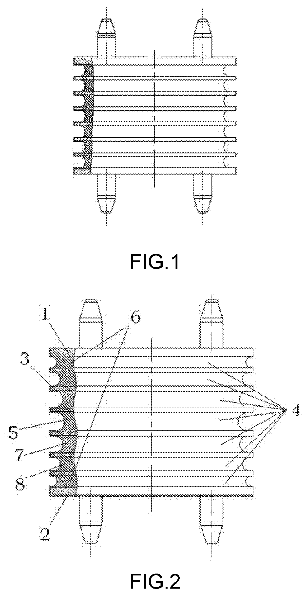
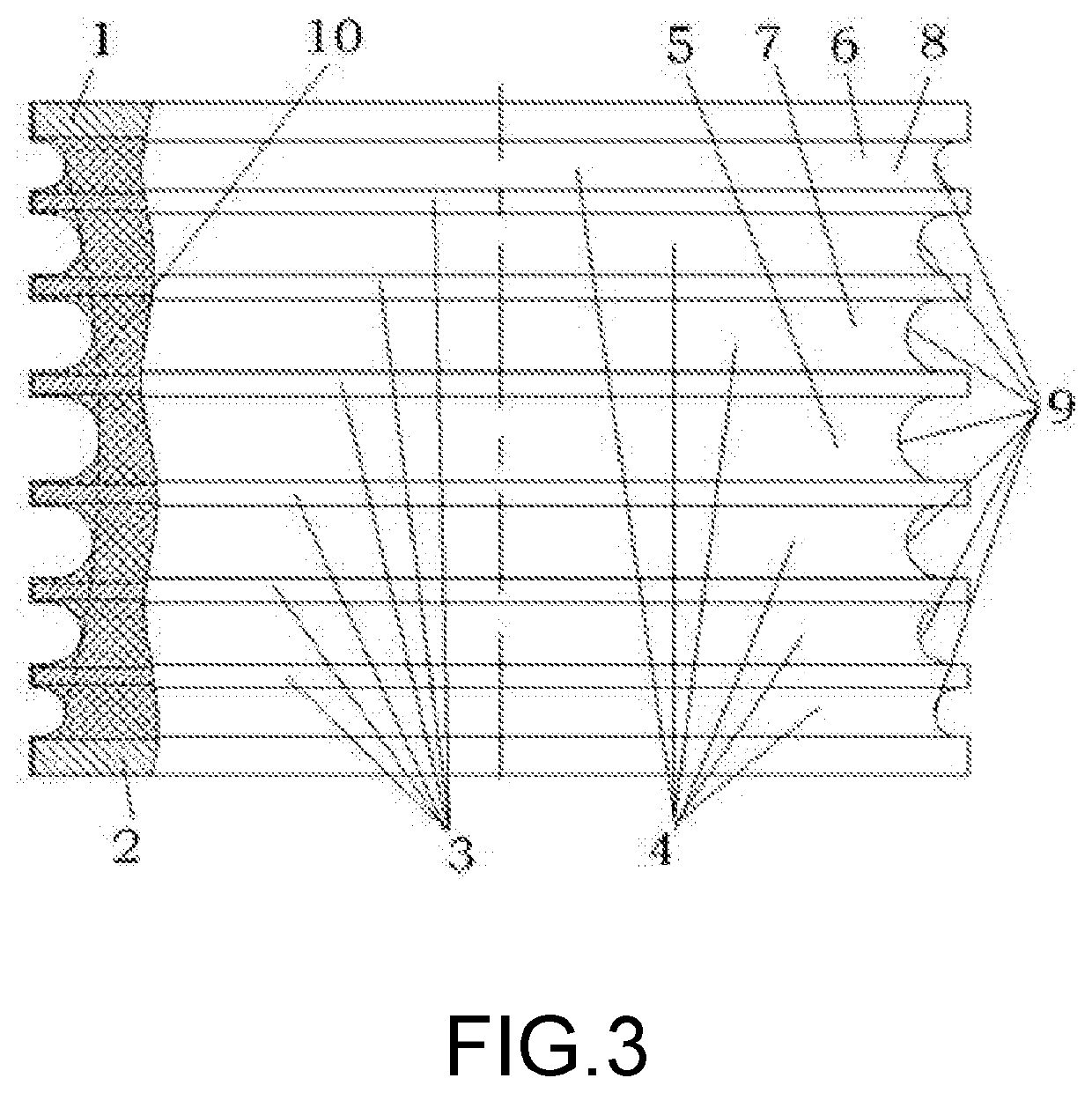
[0023]It can be seen from FIG. 2 and FIG. 3 that the present invention relates to a locomotive rubber-metal pad which includes an upper backing plate 1, a lower backing plate 2, metal partition plates 3 and rubber layers 4. The metal partition plates 3 and the rubber layers 4 are arranged between the upper backing plate 1 and the lower backing plate 2. The rubber layers 4 and the metal layers 3 are staggered to form a rubber-metal pad of rubber and metal with composite layers of rubber and metal, characterized in that the thickness of the rubber layers 4 is variable and the diameter of the rubber layers 4 is also variable.

[0024]The rubber layer 4 uses a middle layer 5 as a reference layer, the middle layer 5 is thickest, the thickness of the rubber layers is gradually reduced from the middle layer 5 to the upper or lower side respectively, and the side or top or bottom rubber layer 6 is thinnest.

[0025]The thickness of the rubber layer is gradually reduced from the middle...

Example

Embodiment 2

[0027]The basic structure of embodiment 2 is the same as that of embodiment 1, and is only different in manufacturing modes. A locomotive rubber-metal pad includes an upper backing plate, a lower backing plate, metal partition plates and rubber layers. The metal partition plates and the rubber layers are arranged between the upper backing plate and the lower backing plate. The rubber layers and the metal layers are staggered to form a rubber-metal pad of rubber and metal with composite layers of rubber and metal, characterized in that the thickness of the rubber layers is variable and the diameter of the rubber layers is also variable.

[0028]Further, the rubber layer uses a middle layer as a reference layer, the middle layer is thickest, the thickness of the rubber layers is gradually reduced from the middle layer to the upper or lower side respectively, and the top or bottom rubber layer is thinnest.

[0029]Further, the thickness of the rubber layer is gradually reduced fr...


PUM


Abstract

A method for improving fatigue resistance performance of a locomotive rubber-metal pad with variable thickness improves the fatigue resistance performance of the rubber-metal pad and prevents rubber and metal from being torn during running by changing a structure of the rubber and the metal of the rubber-metal pad and adjusting a shape and position relationship between the rubber and the metal. The shape and the position relationship of the rubber metal is adjusted by adjusting thickness of a rubber layer between the rubber and the metal of the rubber-metal pad so that the rubber layer has variable thickness. The fatigue resistance performance of the rubber-metal pad is improved by adjusting the thickness of the rubber layer.

Description

BACKGROUNDTechnical Field[0001]The present invention relates to a primary or secondary elastic vibration reduction method and device of a locomotive, and in particular to an elastic vibration reduction method and device for improving fatigue resistance performance of a locomotive rubber-metal pad and preventing the rubber of the rubber-metal pad from being torn. The elastic vibration reduction method and device of the locomotive rubber-metal pad can substantially improve the fatigue resistance performance and durability of the locomotive rubber-metal pad and prevent a rubber layer of the rubber-metal pad from generating a tearing phenomenon, and belong to the technical field of elastic vibration reduction of the locomotive.Description of Related Art[0002]A side bearing of the rubber-metal pad is widely applied to a primary or secondary suspension of the locomotive, is a connecting device between a locomotive body and a bogie, and has the effects of evenly distributing the upper mass...

Claims


Application Information

Patent Timeline
IPC IPC(8): B61F5/08
CPCB61F5/08F16F1/40
Inventor LIU, QINGMEIZHAO, BINYUAN, KEFENG, WANSHENG
Owner ZHUZHOU TIMES NEW MATERIALS TECH
Why Eureka
Try Eureka