Container adapted to function as a dispenser and method of dispensing articles therefrom

Pending Publication Date: 2021-11-11
MULTI COLOR CORP
24 Cites 0 Cited by

AI-Extracted Technical Summary

Problems solved by technology

Once opened by the end user, the targets are loose and unsupported and the potential for damage by mishandling and by curl created by varying humidity is ever-present.
These packs of targets can range in quantity from 4 targets up to we...

Abstract

Apparatus and methods for the dispensing of articles and, more specifically, for the dispensing of stacked articles. The apparatus may be a container including a housing having an upper surface, a lower surface, and at least one side wall. The housing defines an interior chamber; and includes a removable section, wherein removal of the removable section allows access to the interior chamber. A plurality of articles may be disposed within the interior chamber, such as in a stacked configuration. The plurality of articles including at least a first article and a second article, wherein each article has opposite first and second ends, and at least a portion of the second end of the first article is releasably attached to the second end of the second article.

Application Domain

Flat article dispensingWebs handling

Technology Topic

Process engineeringMechanical engineering +1

Image

  • Container adapted to function as a dispenser and method of dispensing articles therefrom
  • Container adapted to function as a dispenser and method of dispensing articles therefrom
  • Container adapted to function as a dispenser and method of dispensing articles therefrom

Examples

  • Experimental program(1)

Example

[0018]One or more specific embodiments of the present invention will be described below. In an effort to provide a concise description of these embodiments, all features of an actual implementation may not be described in the specification. It should be appreciated that in the development of any such actual implementation, as in any engineering or design project, numerous implementation-specific decisions must be made to achieve the developers' specific goals, such as compliance with system-related and business-related constraints, which may vary from one implementation to another. Moreover, it should be appreciated that such a development effort might be complex and time consuming, but would nevertheless be a routine undertaking of design, fabrication, and manufacture for those of ordinary skill having the benefit of this disclosure.
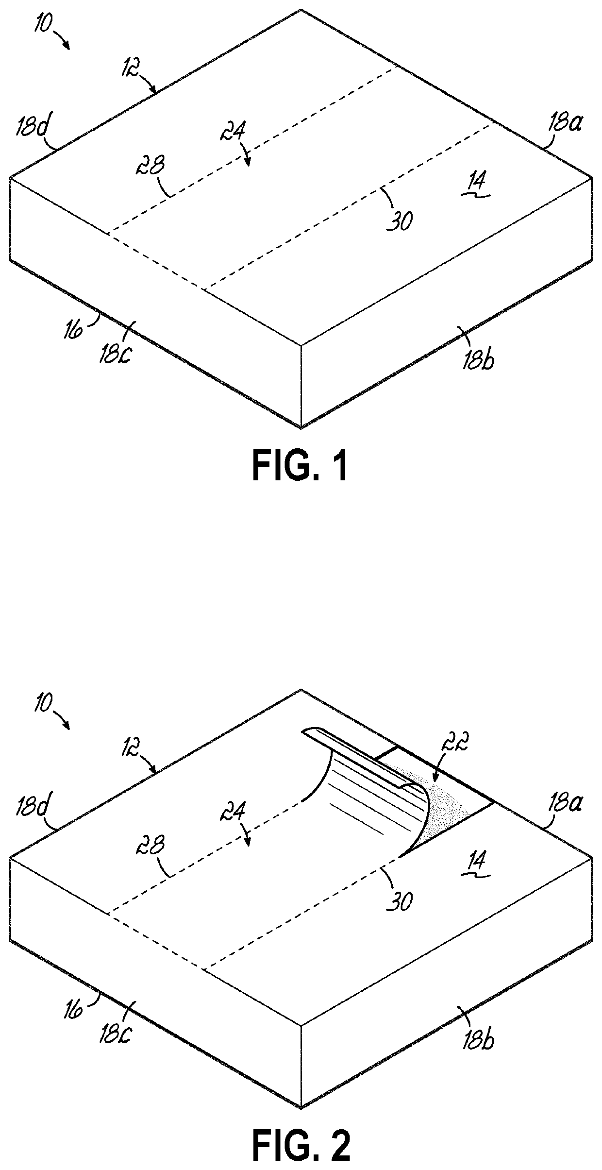
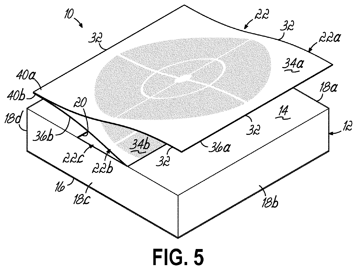
[0019]Examples of a container and a method of operation thereof (in accordance with principles of the present invention) are shown in FIGS. 1-7. The container 10 includes a housing 12 (which, in the illustrated embodiment, may be a container for articles, and particularly for articles having a sheet-like form). The housing 12 of the illustrated embodiment includes an upper surface 14, a lower surface 16, and at least one side wall (the particular embodiment of FIGS. 1-7 includes four side walls 18a, 18b, 18c, 18d). (As can be seen from the figures, with respect to the housing, the “upper” surface thereof refers to the outer surface, and the “lower” surface thereof refers to the inner surface.) The housing 12 defines an interior chamber 20 capable of containing a plurality of sheets 22. In one embodiment, the housing 12 may be made with a paperboard substrate (or other materials) that can contain any number of sheets, and once opened via removable section—the housing 12 functions as a dispenser and a carrier that neatly contains the plurality of sheets 22. In one particular embodiment, the paperboard may be a 16 PT C1S SBS substrate; however, the housing 12 of the container 10 can be made with any number of paperboard thicknesses and grades along with other available packaging substrates, including film-based materials. Certain embodiments may be recyclable; for example, embodiments including a paper-based or paperboard substrate may be recyclable The container 10 can be sized to accommodate sheets of all sizes and shapes. Thus, while the figures show a housing 12 having a particular shape, materials, etc., it will be recognized by those of ordinary skill in the art that a container 10 in accordance with the principles of the present invention may be of any other shape, materials, etc.
[0020]As shown in the figures, the upper surface 14 of the housing 12 may include a removable section 24 (see FIGS. 1-3). Removal of removable section 24 allows access to the plurality of sheets 22 contained within the interior chamber 20 of the housing 12 via an opening 26 in upper surface 14 that is present once removable section 24 is removed. Removable section 24 may be formed by any method known to those of ordinary skill in the art—such as by being a portion initially integral with remainder of upper surface 14, and being defined by and removable by perforations at two edges 28, 30 of removable section 24; or by being a separate section that is removably adhered to an opening 26 in the upper surface 14. Removable section 24 may also be designed to be capable of being re-affixed, re-adhered, or otherwise replaced over opening 26. Removable section 24 may be fully removed during use, or may be pulled away from upper surface 14 to expose opening 26 while remaining attached to upper surface 14 (such as by being hinged at one end thereof).
[0021]As described above, the container 10 further includes a plurality of sheets 22 positioned within the interior chamber 20 of the housing 12 of the container 10. The plurality of sheets 22, as in the illustrated embodiment, includes two or more sheets releasably attached to one another in a stack configuration.
[0022]As shown particularly in FIG. 5, each sheet of the plurality of sheets 22 includes a plurality of edges 32 (in the illustrated embodiment, each sheet is of a substantially square shape having four edges). Each sheet has opposite upper and lower surfaces and opposite first and second ends (the first and second ends including first and second edges, respectively). (“Upper” and “lower,” with respect to the surfaces of the sheets, are used referring to the orientation shown in the Figures. It will be recognized that this orientation is not dependent on orientation of the housing—and sheets within—relative to the surface of the Earth. In other words, the surface of the sheets facing toward the removable section, as shown in the Figures, is the upper surface, and the opposite surface is the lower surface.)
[0023]In an exemplary embodiment, the plurality of sheets 22 includes first sheet 22a and second sheet 22b. At least a portion of the lower surface 36a of the first sheet 22a may have an adhesive thereon. The portion of the lower surface 36a with the adhesive may be second end 40a of the first sheet 22a. The first end 38a of the first sheet 22a is free of adhesive. Adhesive on the lower surface 36a of second end 40a of first sheet 22a contacts the upper surface 34b of the second end 40b of second sheet 22b (such that the adhesive is positioned between the second ends 40a, 40b of first and second sheets 22a, 22b). As one grasps the first end 38a of first sheet 22a and removes first sheet 22a from housing 12, the second end 40a of first sheet 22a and the second end 40b of second sheet 22b will also be pulled from the housing 12 (see FIGS. 4 and 5) due to a pulling force being exerted on second sheet 22b that causes second end 40b of second sheet 22b through opening 26 in housing 12. The adhesive between second ends 40a, 40b of first and second sheets 22a, 22b is a releasable adhesive such that the first sheet 22a may then be separated from second sheet 22b (thus, leaving second sheet 22b partially disposed within interior chamber 20 of housing 12, but with second end 40b thereof exposed outside of housing 12).
[0024]As described above, a plurality of sheets 22 may be combined to form a stack of sheets in the housing 12 of the container 10. Thus, in addition to the first and second sheet 22a, 22b mentioned above, the plurality of sheets 22 may further include third, fourth, fifth, etc. sheets. Thus, a third sheet 22c may be present adjacent second sheet 22b (see FIG. 5). However, the positioning of the adhesive between second and third sheets 22b, 22c is different that position of adhesive between first and second sheets 22a, 22b. The lower surface 36b of second end 40b of second sheet 22b does not include adhesive. Rather, the portion of the lower surface including adhesive may be first end of the second sheet. Adhesive on the lower surface of first end of second sheet contacts the upper surface of the first end of third sheet 22c (such that the adhesive is positioned between the first ends of second and third sheets 22b, 22c). As one grasps the second end 40b of second sheet 22b and removes second sheet 22b from housing 12, the first end of second sheet and the first end of third sheet will also be pulled from the housing 12 (not shown). The adhesive between first ends of second and third sheets 22b, 22c is a releasable adhesive such that the second sheet 22b may then be separated from third sheet 22c (thus, leaving third sheet 22c partially disposed within interior chamber 20 of housing 12, but with first end thereof exposed outside of housing 12). For any remaining sheets in the interior chamber 20, the position of releasable adhesive will alternate from being between first ends 38 of adjacent sheets to being between second ends 40 of adjacent sheets. The removal process of sheets described above can then be repeated to remove each successive sheet from housing 12 as desired.
[0025]Above, adhesive may be described as being on a lower surface of a first sheet and adhered to upper surface of a second sheet. Those of ordinary skill in the art will recognize that, alternatively, adhesive may be positioned on upper surface of second sheet to adhere to lower surface of first sheet. Either arrangement results in an adhesive that is positioned between the two sheets in order to releasably adhere first and second sheets to one another at end. Alternatively, adhesive may be positioned along adjacent edges of successive sheets (such as first and second sheets).
[0026]In certain embodiments, the adhesion of sheets to one and another may occur via small dots [or other forms such as lines of adhesive or glue (e.g., straight or wavy lines), screened patterns, boxes, etc.] of adhesive or glue that are alternately placed on the first and second ends of the sheets in a sequence that allows a back-and-forth dispensing action as the sheets are pulled from the container 10, thereby allowing quick and easy access to the next available sheet. The adhesive used can be any number of adhesive/glue types that could include but not limited to hot melts, emulsions, and solvent-based products.
[0027]An alternate embodiment of the plurality of sheets 22 is shown in FIG. 6. In this embodiment, the plurality of sheets 22 may include perforations 42 between each sheet to allow the same dispensing without the need of adhesive (in the embodiment shown in FIG. 5). Thus, in the embodiment shown in FIG. 6, each sheet of the plurality of sheets 22 includes a plurality of edges 32 (in the illustrated embodiment of FIG. 6, each sheet is of a substantially square shape having four edges—but may also be a non-square shape or a special shape such as a pentagon, squircle, or the likeness of animate beings, etc.). Each sheet has opposite upper and lower surfaces 34, 36 and opposite first and second ends 38, 40 (the first and second ends including first and second edges, respectively). In an exemplary embodiment, the plurality of sheets 22 includes first sheet 22a and second sheet 22b. A first perforation 42 is formed to delineate first sheet 22a from second sheet 22b, such that the first perforation 42 forms a boundary between the second end 40a of the first sheet 22a and the second end 40b of the second sheet 22b (i.e., first perforation 42 is positioned between the second ends 40a, 40b of first and second sheets 22a, 22b). Perforations may be formed by cutting a sheet substrate via a steel to steel tool leaving a quantity of uncut arears that result in the attachment of the sheets to each other. As one grasps the first end 38a of first sheet 22a and removes first sheet 22a from housing 12, the second end 40a of first sheet 22a and the second end 40b of second sheet 22b will also be pulled from the housing 12 due to a pulling force being exerted on second sheet 22b that causes second end 40b of second sheet 22b through opening 26 in housing 12. The first sheet 22a may then be separated from second sheet 22b by tearing along first perforation 42 (thus, leaving second sheet 22b partially disposed within interior chamber 20 of housing 12, but with second end 40b thereof exposed outside of housing 12). The plurality of sheets 22 may then include further perforations (i.e., second, third, fourth perforations, etc.) providing boundaries and allowing for dispensing and separation of further sheets (i.e., second, third, fourth sheets, etc.) in similar manner as described above with respect to embodiment having adhesive in FIG. 5. FIG. 7 shows first sheet 22a being separated from second sheet 22b, such as along perforations 42.
[0028]Those of ordinary skill in the art will recognize that other mechanical means of releasably joining two adjacent sheets are possible, such as coining or embossing, for example.
[0029]While the present invention has been disclosed by reference to the details of preferred embodiments of the invention, it is to be understood that the disclosure is intended as an illustrative rather than in a limiting sense, as it is contemplated that modifications will readily occur to those skilled in the art, within the spirit of the invention and the scope of the amended claims.

PUM

no PUM

Description & Claims & Application Information

We can also present the details of the Description, Claims and Application information to help users get a comprehensive understanding of the technical details of the patent, such as background art, summary of invention, brief description of drawings, description of embodiments, and other original content. On the other hand, users can also determine the specific scope of protection of the technology through the list of claims; as well as understand the changes in the life cycle of the technology with the presentation of the patent timeline. Login to view more.
Why Eureka
Try Eureka