
Breath sampling interface

a sampling interface and breathing technology, applied in the field of respiratory gas therapy, can solve the problems of affecting the quality of life of patients, and affecting the quality of life of patients, and the process of gas sampling is fraught with difficulties, and the end of the sampling conduit can become blocked by. current methods do not allow for simple repositioning of the sampling interfa

Pending Publication Date: 2021-12-02
FISHER & PAYKEL HEALTHCARE LTD
View PDF0 Cites 1 Cited by
  • Summary
  • Abstract
  • Description
  • Claims
  • Application Information

AI Technical Summary

Benefits of technology

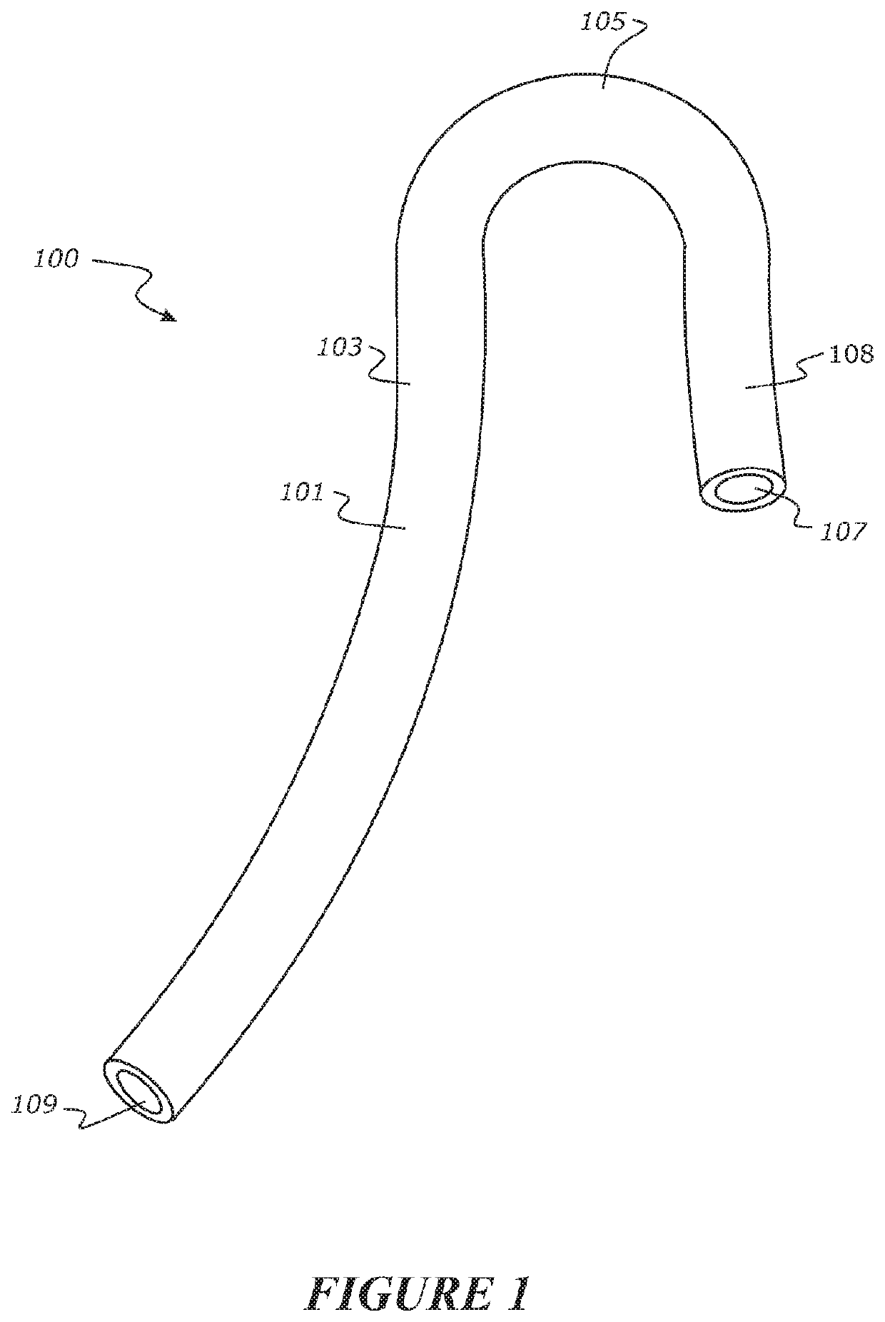
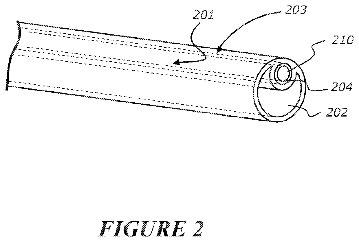
The patent describes a gas sampling interface for patients that can be used to collect gases exhaled or expired by a patient. The interface includes a conduit with a hook portion for engaging with the patient's face or mouth. The hook portion can be adjustable to fit different patients. The conduit has a single or double lumen, and can be connected to a sampling tube through a luer. The interface can also be attached to a nasal cannula or other breathing apparatus. The technical effects of the invention include improved gas sampling for patients and the ability to collect gases from patients with a simple and adjustable interface.

Problems solved by technology

Although gas sampling is commonly used with anaesthetised patient's, known gas sampling interfaces, gas sampling conduits, and processes for gas sampling are fraught with difficulties.
Further, if a portion of the sampling conduit is positioned inside the patient's mouth, the end of the sampling conduit can become blocked by saliva or blood or can suction onto the inside of the patient's cheek or onto the patient's tongue.
Current methods do not allow for simple repositioning of the sampling interface when required.
For example, reliable CO2 sampling may be difficult when it is unclear in advance of a procedure whether a patient will breathe predominantly from the nose or mouth.
Repositioning of the sampling conduit in this manner requires the sampling conduit attachment procedure to be repeated, which is time consuming.
Gas sampling is particularly difficult when a patient is apnoeic because the amount of gas exiting or expired out of the lungs of an apnoeic patient is very low.
Expired CO2 (which may simply diffuse from an apnoeic patient's airways) cannot accurately be detected in the nose or mouth because there is no patient ventilation to effectively expel the gas that far from the lungs and any gas that exits at the nose or mouth is significantly diluted.
However, sampling at the back of the throat creates difficulties during procedures that require access to the patient's airways, such as during oral procedures where the sampling interface may interfere with a surgeon's tools.
It is also difficult and sometimes impossible to intubate a patient undergoing an oral surgical procedure.
Low flow cannulas typically cannot provide breathing gas at flow rates above 15 L / min.
The nature of high flow therapy creates significant dilution of the expired gas from the patient, making it difficult to accurately measure CO2 and other expired gases.
However, monitoring CO2 or other expired and / or exhaled gases whilst also supplying high flow therapy (supplying breathing gas to a patient at high flow rates though a breathing apparatus) is difficult.
This is due to the flushing mechanism provided by high flow therapy that alters the flow pattern within the anatomical dead space, causing a non-uniform distribution of expired gas.
When the non-uniform gas distribution is sampled from the nose and / or mouth, an invalid quantitative measurement is made by a standard respiratory gas monitor in a gas sampling system.
However, the cannula is not suitable for delivering high flow therapy, for delivery therapy through both nares of a patient's nose, or for allowing selective gas sampling from the nose or the mouth.

Method used


Image

  • Breath sampling interface
  • Breath sampling interface
  • Breath sampling interface

Examples


Embodiment Construction

[0154]In general, the invention relates to a respiratory gas delivery and sampling system, a gas sampling system, a gas sampling interface and a gas sampling tip that may be used to sample exhaled and / or expired gases from a patient. The gas sampling system comprises a respiratory gas monitor in fluid communication with the gas sampling interface, which comprises the gas sampling tip of the invention. The gas sampling interface comprises a gas sampling conduit and the gas sampling tip is located at a free end of the conduit. The gas sampling interface may be configured to allow the gas sampling tip to be selectively positioned at or in the mouth or a nare of the patient's nose. The sampling tip comprises at least one inlet to receive exhaled or expired gas from a patient. The sampling tip may also be configured to comprise a shield or structure that helps prevent fluid, such as moisture or bodily fluids from entering into the sampling tip. Additionally or alternatively, the sampling...


PUM


Abstract

There is provided a a respiratory gas delivery and sampling system, a gas sampling system, a gas sampling interface and a gas sampling tip that may be used to sample exhaled and / or expired gases from a patient, particularly from a patient who is apnoeic and / or who is receiving high flow respiratory therapy. The gas sampling system comprises a respiratory gas monitor in fluid communication with the gas sampling interface, which comprises the gas sampling tip of the invention. The gas sampling interface comprises a gas sampling conduit and the gas sampling tip is located at a free end of the conduit. The gas sampling interface may be configured to allow the gas sampling tip to be selectively positioned at or in the mouth or a nare of the patient's nose.

Description

TECHNICAL FIELD[0001]The present disclosure generally relates to respiratory gas therapy. More particularly, the present disclosure relates to an interface for capturing exhaled and / or expired gases, such as CO2, in proximity of a patient's nose or mouth while the patient is being supplied with respiratory gas by a breathing apparatus. In use, the interface comprises or is typically fluidly connected to a gas sampling conduit which is fluidly connected to a respiratory gas monitor. The interface may be particularly useful when measuring exhaled and / or expired gases from a patient receiving high flow respiratory gas.DESCRIPTION OF THE RELATED ART[0002]In medical environments, it is common practice to monitor the concentration of gases exhaled and / or expired by a patient using a gas sampling system comprising a respiratory gas monitor that connects to a gas sampling interface comprising a gas sampling conduit to transfer exhaled and / or expired gas from a patient to the respiratory gas...

Claims


Application Information

Patent Timeline
Patent Type & Authority Applications(United States)
IPC IPC(8): A61M16/08A61M16/06
CPCA61M16/085A61M2210/0618A61M2240/00A61M16/0666A61B5/082A61B5/097A61B5/6819
Inventor CHILCOTT, KATE JAYNEWHITE, CRAIG KARLOLDFIELD, SAMANTHA DALEEVANS, EDWARD JOHN
Owner FISHER & PAYKEL HEALTHCARE LTD
Learn More