System and method for active cancellation for pressure pulses

a technology of active cancellation and pressure pulse, which is applied in the field of monitoring arts, respiration arts, pressure pulsation monitoring arts, and pressure pulsation cancellation arts, can solve the problems of significant pressure variation, significant physical volume, and significant interference with flow rate measurement and gas concentration measurement, so as to remove pressure pulsations, control flow, and remove pressure pulsations

Inactive Publication Date: 2021-05-06
KONINKLJIJKE PHILIPS NV
View PDF10 Cites 0 Cited by
  • Summary
  • Abstract
  • Description
  • Claims
  • Application Information

AI Technical Summary

Benefits of technology

[0010]One advantage resides in removing pressure pulsations in an air pressure signal.
[0011]Another advantage resides in measuring gases in air without pressure pulsations.
[0012]Another advantage resides in controlling flow in a pump by removing pressure pulsations.
[0013]Another advantage resides in measure concentrations of different gases in respired air.

Problems solved by technology

By the reciprocating nature of their operation, such pumps tend to move the sample gas in a pulsatile manner, producing significant pressure variation, i.e. ripple, in the sample line, especially in the vicinity of the pump.
These pressure variations, depending upon their magnitude and frequency, can interfere with flow rate measurement and gas concentration measurement.
Both of these methods have disadvantages.
The reservoir approach, while effective, adds significant physical volume, which is disadvantageous where space is at a premium, and there is significant desire to reduce the physical volume of RGMs.
The low-pass filtering approach adds little physical volume, but does nothing to attenuate or eliminate the pressure pulsation in the gas sampling system.
Since the pulsations can be very large compared to the pressure drop associated with flow, this creates a risk of pressure sensor saturation unless a sensor with a very wide pressure sensing range is employed.
If the sensor saturates, the low-pass method produces an error in flow rate measurement, but selecting a wide-range sensor (compared to the desired measurement) usually results in poor measurement accuracy unless a very expensive, high-accuracy sensor is chosen.
Further, this technique permits the un-attenuated pressure pulsations to appear in the measurement area, producing errors in the measurement of gas concentrations.

Method used


Image

  • System and method for active cancellation for pressure pulses
  • System and method for active cancellation for pressure pulses

Examples


Embodiment Construction

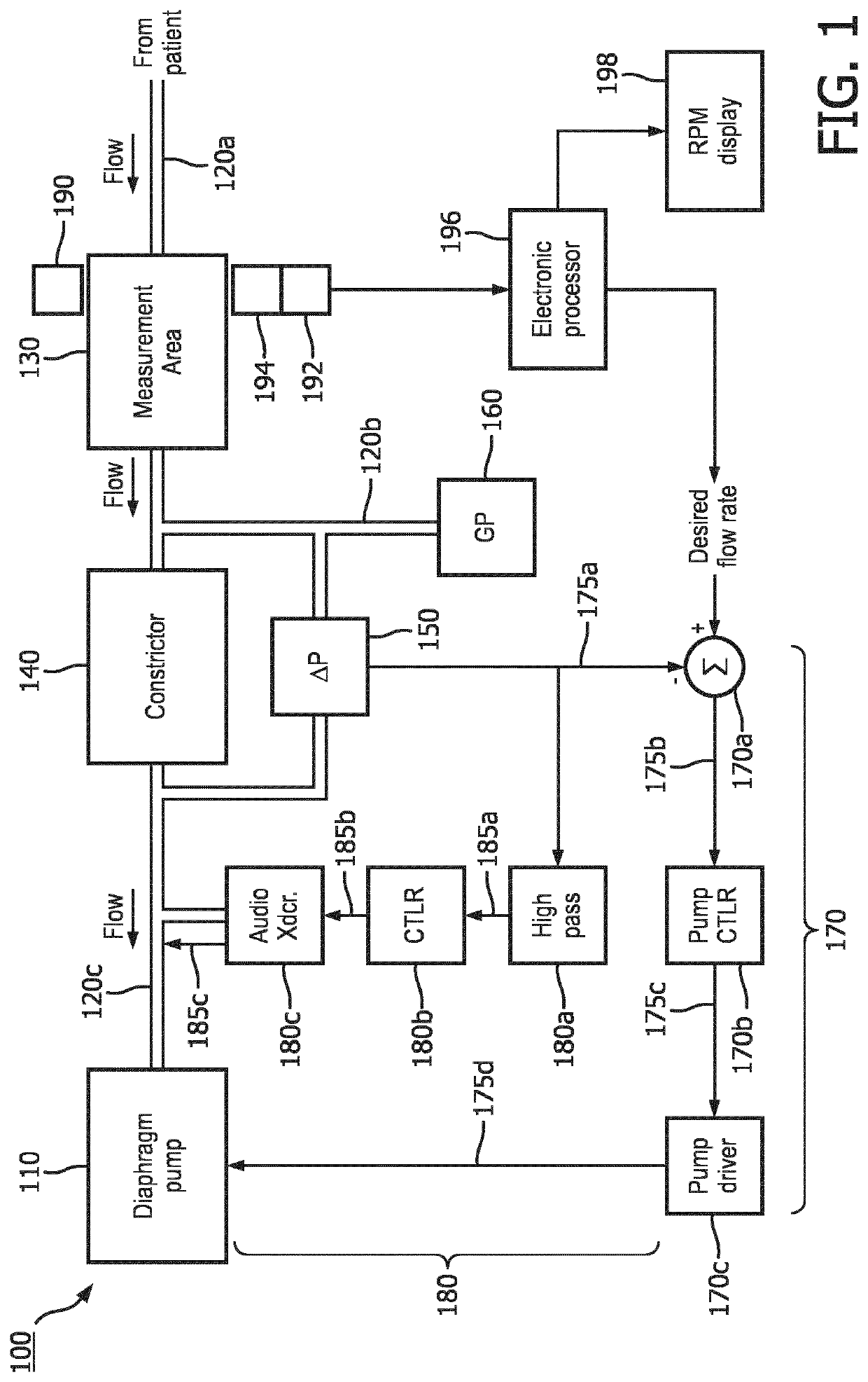
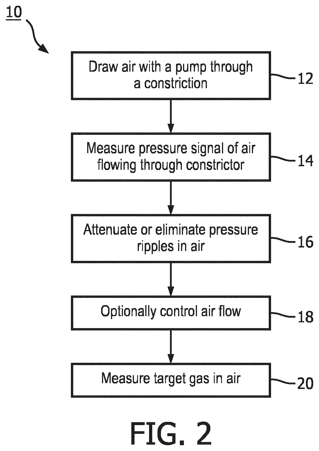
[0018]In RGMs, the respiration gas flow is typically regulated to a relatively constant rate to avoid temporal distortion of the gas concentration record (i.e., waveform). This flow regulation is often accomplished by introducing a constrictor (such as an orifice or a capillary tube) into the gas flow path and controlling the pump drive level is controlled to maintain a constant pressure drop across the constrictor. Since the pressure drop is a direct function of the flow rate, maintaining a constant pressure drop produces a constant flow rate. In the presence of pump-induced pressure pulsations, however, the amplitude of the pulsations in the pressure drop can be large, and may even exceed the magnitude of the flow-induced pressure drop, which can be problematic for accuracy of the flow rate measurement and control.

[0019]Another problem potentially introduced by pressure pulsations in the sample line is that the pressure pulsations appear on the gas sample in the measuring area of ...


PUM


Abstract

A respiration gas monitor device (100) includes a pump (110) connected to draw a flow of respired air, a pressure sensor (150, 160) is connected to measure an air pressure signal responsive to the flow of respired air, and a pressure transducer (180c). Electrical circuitry (170, 180) is operatively connected to measure flow across the pressure sensor. A gas component sensor (190, 192,194) is arranged to monitor a target gas in the flow of respired air.

Description

FIELD[0001]The following relates generally to the monitoring arts, respiration arts, pressure pulsation monitoring arts, pressure pulsation cancellation arts, gaseous concentration measurement arts, and related arts.BACKGROUND[0002]In sidestream respiration gas monitors (RGMs), also known as diverting RGMs, a sample of respiration gas is drawn from a patient down a sample tube to a measuring area of the RGM (respiration gas monitor) where any of a variety of techniques can be used to measure the concentration of one or more components of the respiration gas including, but not limited to, carbon dioxide (CO2), oxygen (O2), nitrous oxide (N2O), and halogenated agents such as halothane, enflurane, isoflurane, sevoflurane and desflurane. Patterns of variation in the concentrations of these gas components can have clinical significance in the treatment of patients. Accordingly, it is desired to provide a consistent, accurate temporal record of the monitored gas concentration to aid in th...

Claims


Application Information

Patent Timeline
Patent Type & Authority Applications(United States)
IPC IPC(8): A61B5/08A61B5/00A61B5/087A61B5/097
CPCA61B5/082A61B5/0803A61B5/7203A61B2562/0247A61B5/087A61B5/097A61B5/0082A61B5/7225A61B2562/0233
Inventor GERETY, EUGENE PETER
Owner KONINKLJIJKE PHILIPS NV
Why Eureka
Try Eureka