An electro-hydraulic control device for an anti-escape restraint device

A restraint device and electro-hydraulic control technology, which is applied in the direction of fluid pressure actuation device, servo motor, mechanical equipment, etc., can solve the problems of poor blood circulation of the local skin, physical damage of the restrained object, and difficulty in controlling the size of the restraint force. The effect of light weight, avoiding physical damage, ensuring safety and working stability

Inactive Publication Date: 2016-08-24
YANSHAN UNIV
View PDF6 Cites 0 Cited by
  • Summary
  • Abstract
  • Description
  • Claims
  • Application Information

AI Technical Summary

Problems solved by technology

The size of the restraint force of this type of restraint device is not easy to control, the reliability is not high, it consumes manpower, and it is easy to cause physical damage to the restrained object. Tight and lead to poor blood circulation in the local skin, resulting in damage

Method used


Image

  • An electro-hydraulic control device for an anti-escape restraint device
  • An electro-hydraulic control device for an anti-escape restraint device
  • An electro-hydraulic control device for an anti-escape restraint device

Examples


Embodiment 1

[0035] Embodiment 1: The system implementation mode of the electro-hydraulic control system.

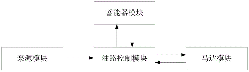
[0036] An electro-hydraulic control device of an anti-dropping restraint device, such as figure 1 As shown, including pump source module, oil circuit control module, accumulator module and motor module;

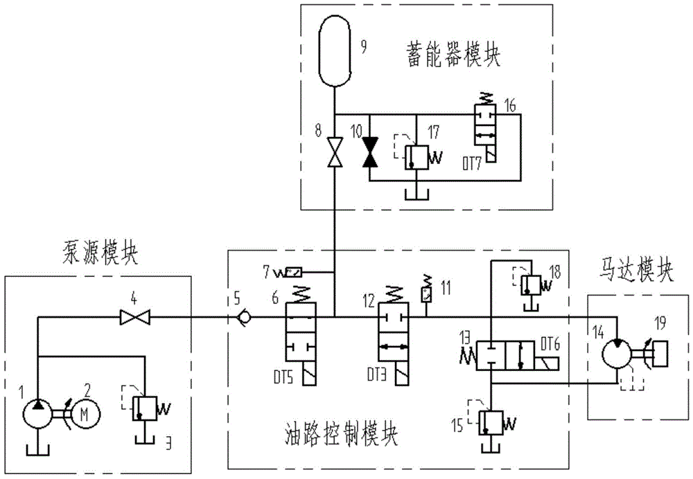
[0037] Such as figure 2 As shown: the pump source module includes a hydraulic pump 1, a motor 2, a first relief valve 3 and a first stop valve 4. The hydraulic pump 1 and the motor 2 are connected by a coupling, and the inlet of the hydraulic pump 1 is connected to the oil tank, Its outlet is connected to the first relief valve 3, and the oil return port of the first relief valve 3 is connected to the oil tank. At the same time, the outlet of the hydraulic pump 1 is connected to the first stop valve 4, and the first stop valve 4 is connected to the one-way of the oil circuit control module. Valve 5;

[0038] The oil circuit control module includes a one-way valve 5, a first electromagnet...

Embodiment 2

[0046] The second embodiment: the implementation of the hydraulic control system.

[0047] A hydraulic control device of an anti-off restraint device, such as figure 1 As shown, including pump source module, oil circuit control module, accumulator module, motor module;

[0048] The pump source module and the motor module are the same as those in the hydraulic system of the electro-hydraulic control system.

[0049] Such as image 3 As shown, the oil circuit control module includes a one-way valve 20, a hydraulic reversing valve 21, a manual reversing valve 23, a second overflow valve 24, and a safety valve 22. One end of the one-way valve 20 is connected to the first pump module. A stop valve 4, the other end of which is connected to the hydraulic directional valve 21, the hydraulic oil is divided into three paths after passing through the hydraulic directional valve 21, of which: one path goes through the safety valve 22 and then returns to the tank, and the second path of hydraulic...


PUM


Abstract

The invention discloses an electro-hydraulic control device of an anti-off restraint device, which includes a pump source module, an oil circuit control module, an accumulator module, and a motor module; the pump source module includes a hydraulic pump, a motor, a first overflow valve and a second overflow valve. A cut-off valve; the oil circuit control module includes a one-way valve, a first electromagnetic reversing valve, a second electromagnetic reversing valve, a third electromagnetic reversing valve, a second relief valve and a safety valve, a first pressure relay, a second The pressure relay; the accumulator module includes an accumulator, the second shut-off valve, the third shut-off valve, the third overflow valve, and the fourth electromagnetic reversing valve; the motor module includes a motor and a restraint belt fixing device. The device of the invention has high degree of automation, can be remotely controlled, and the output torque can be precisely adjusted with a large adjustment range, and the object will not be damaged while being restrained. The present invention can adopt both the electro-hydraulic control mode and the hydraulic control mode, and can meet the different requirements of the user for high automation, low cost, and harsh working conditions.

Description

Technical field [0001] The invention relates to a control device, in particular to an electro-hydraulic control device of an anti-release restraint device. Background technique [0002] In the field of restraint for mental patients, criminals, and goods with anti-damage requirements, the existing restraint devices are all manually operated, relying on rigid or flexible locking of mechanical structures, such as binding the restrained objects with restraint belts. The restraining force of this kind of restraint device is not easy to control, is not reliable, consumes manpower, and is likely to cause physical damage to the restrained object. For example, the local skin tissue of a mental patient in an unstable state is bound by the restraint belt during the resistance process. Tightness leads to poor blood circulation in the local skin, causing damage. Summary of the invention [0003] The purpose of the present invention is to overcome the shortcomings in the prior art and provide ...

Claims


Application Information

Patent Timeline
Patent Type & Authority Patents(China)
IPC IPC(8): F15B1/02F15B11/028
Inventor 郭锐赵静一张毅
Owner YANSHAN UNIV
Why Eureka
Try Eureka