Vortex liquid pump capable of preventing pressure pulsation

A technology of pressure pulsation and moving vortex, applied in the direction of rotary piston/oscillating piston pump components, rotary piston pumps, pumps, etc., can solve problems such as inapplicability, complex system structure, and increased leakage

Active Publication Date: 2021-06-08
QINGDAO UNIV OF SCI & TECH
View PDF8 Cites 0 Cited by
  • Summary
  • Abstract
  • Description
  • Claims
  • Application Information

AI Technical Summary

Problems solved by technology

[0007] Option 1 refers to the method of opening the pressure relief groove at a specific position according to the motion characteristics of the movable scroll. Since the shape of the groove is related to its involute, in its It is difficult to process and design. If the groove shape is not handled properly, it will lead to increased leakage and affect the efficiency of the pump; if the groove depth is too small, the liquid will not be discharged in time, and if the groove depth is large, it will affect the rigidity of the end cover.
[0008]Proposed by the second scheme, a group of flow holes is set between a group of synchronously operating expansion-type vortex pairs and contraction-type vortex pairs that generate pressure pulsation in the closed cavity method, because the system structure is too complex, so the application field is too limited, not suitable for a single pump

Method used


Image

  • Vortex liquid pump capable of preventing pressure pulsation
  • Vortex liquid pump capable of preventing pressure pulsation
  • Vortex liquid pump capable of preventing pressure pulsation

Examples


Embodiment 1

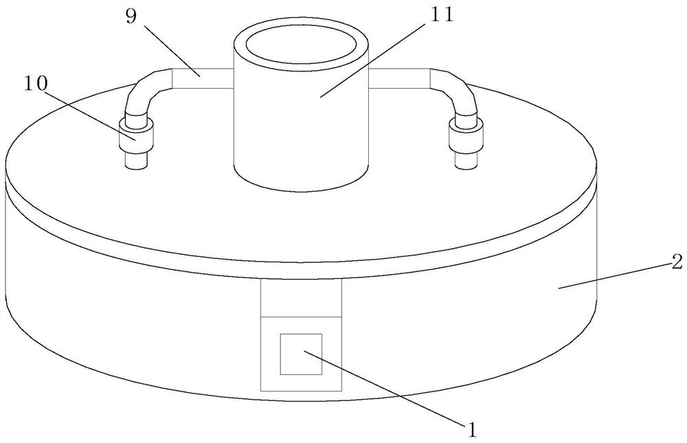
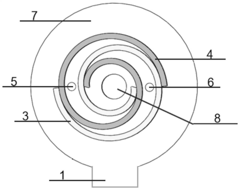
[0030] Such as Figure 1-4 As shown, the present invention is a scroll pump that prevents pressure pulsation, including a support housing 2, a static scroll 3, a movable scroll 4, a static scroll end cover 7, and the static scroll 3 The fixed scroll end cover 7 is fixed, and the movable scroll 4 is disposed in the support housing 2, and the support housing 2 and the static scroll end cover 7 form a closed cavity and the static scroll 3, The scroll 4 is disposed within the enclosed cavity; the movable scroll 4 is mounted between 180 ° phase angles and forms a moon-shaped working chamber between 180 ° phase angles and the static scroll 3; the movable scroll 4 is connected The mechanism, the movable scroll 4 is rotationally moved by the power mechanism to the static scroll 3; there is a discharge port 8 in the middle of the static scroll end cap 7, and the support housing 2 is provided with an inlet port. 1; the closed chamber is provided with a pressure regulation structure that adju...

Embodiment 2

[0034] Such asFigure 5-7 As shown, a scroll pump that prevents pressure pulsation includes a support housing 2, a static scroll 3, a movable scroll 4, a static scroll end cover 7, and the static scroll 3 is fixedly disposed. On the scroll end cover 7, the movable scroll 4 is disposed within the support housing 2, and the support housing 2 and the static scroll end cover 7 form a closed cavity and the static scroll 3, the scroll rotary disc 4 is disposed within the enclosed cavity; the movable scroll 4 is mounted between 180 ° phase angles and forms a pitch working chamber between 180 °; the movable mechanism is connected. The scroll 4 is rotationally motion in the drive of the power mechanism, and a discharge port 8 is provided in the middle of the static scroll end cap 7, and a support housing 2 is provided with an inlet 1; enclosed An adjustment of the moonstone working chamber pressure is provided in the cavity.

[0035] The pressure regulating structural pressure regulating st...

Embodiment 3

[0039] A scroll pump that prevents pressure pulsation, including support housing 2, static scroll 3, movable scroll 4, static scroll end cover 7, said static scroll 3 fixedly disposed in a static scroll On the end cap 7, the movable scroll 4 is disposed within the support housing 2, and the support housing 2 is fitted with the static scroll end cap 7 to form a closed cavity and the static scroll 3, and the scroll 4 is disposed. In the enclosed cavity; the movable scroll 4 and the static scroll 3 are mounted in a 180 ° phase angle and form a pair of moon tooth working cavity; the movable scroll 4 is connected to a power mechanism, a movable scroll 4 In the drive of the power mechanism, the swivel vortex 3 is rotationally moved; and there is a discharge port 8 in the middle portion of the static scroll end cover 7, and the support housing 2 is provided with an inlet port 1; enclosed in the cavity There is a pressure regulating structure that adjusts the moonstone working chamber pre...


PUM


Abstract

The invention discloses a vortex liquid pump capable of preventing pressure pulsation. The vortex liquid pump is characterized in that the vortex liquid pump comprises a supporting shell (2), a static vortex plate (3), a dynamic vortex plate (4) and a static vortex plate end cover (7), the static vortex plate (3) is fixedly arranged on the static vortex plate end cover (7), the dynamic vortex plate (4) is arranged in the supporting shell (2), the supporting shell (2) is matched with the static vortex plate end cover (7) to form a closed cavity, and the static vortex plate (3) and the dynamic vortex plate (4) are arranged in the closed cavity; the dynamic vortex plate (4) is connected with a power mechanism, the dynamic vortex plate (4) is driven by the power mechanism to rotate relative to the static vortex plate (3), and a crescent working cavity is formed between the static vortex plate (3) and the dynamic vortex plate (4). The vortex liquid pump has the advantages that on the premise that the structure of the vortex liquid pump is kept simple, pressure pulsation is eliminated, and vibration, caused by pressure pulsation, of the vortex liquid pump is reduced.

Description

Technical field [0001] The present invention relates to a scroll pump that prevents pressure pulsation, belongs to the field of pump equipment. Background technique [0002] Under the crankshaft drive, the movable disc is rotated around the static disk, and the fixed swivel radius is not rotated. The moon can move toward the center, and the volume is constantly narrowing and the pressure is constantly rising until the center of the discharge port is connected to the center. The pump body is discharged, thereby achieving liquid suction, extrusion and discharge process. [0003] The vortex pump is within a certain angle of operation of the scroll pump due to its inherent working characteristics, since the volume of the formed crescent-shaped working cavity does not communicate with the discharge chamber, and the cumshot working cavity and drainage In a certain angle of circulation after the chamber, the flow area between the two is slowly increased, and the amount of liquid require...

Claims


Application Information

Patent Timeline
Patent Type & Authority Applications(China)
IPC IPC(8): F04C2/02F04C15/00F04C14/24
CPCF04C2/025F04C15/0049F04C15/00F04C14/24F04C2240/20
Inventor 赵远扬田素根杨启超刘广彬李连生
Owner QINGDAO UNIV OF SCI & TECH
Why Eureka
Try Eureka