A pneumatic arrangement of a less-lethal device

a less-lethal and pneumatic technology, applied in the direction of safety arrangement, compressed gas guns, white arms/cold weapons, etc., can solve the problems of excessive force, inability to comply with proposed legislative provisions, and ineffective lethal devices

Active Publication Date: 2021-12-09
BYRNA TECH INC
View PDF34 Cites 2 Cited by
  • Summary
  • Abstract
  • Description
  • Claims
  • Application Information

AI Technical Summary

Benefits of technology

[0021]The displaceable body may be provided with a peripheral seal received within a peripheral groove, the seal for sealing within the housing, thereby to inhibit compressed gas from operatively escaping between the housing and the displaceable body.
[0039]a stop member formed on the displaceable body, receivable within an internal slot formed on the housing, so that when the stop member is received within the internal slot, the displaceable body is prevented from articulating relative to the housing;
[0050]According an alternative example of the first aspect of the invention, the puncture mechanism may further comprise a sealing body, received within the housing, displaceable between a forward and a rearward position relative to the housing, the sealing body comprising an annular seal which operatively seals against the mouth of the canister. The sealing body may furthermore comprise an internal bore for receiving a leading portion of the displaceable body. The displaceable body may comprise a shoulder for urging the sealing body towards the canister, when the displaceable body is located in the second position. A seal may be provided between the leading portion of the displaceable body and the internal cavity for operatively preventing compressed gas from leaking between the displaceable body and the sealing body.
[0068]an adjusting mechanism for adjusting the follower body to cause the first and second arms of the torsion spring to be adjusted angularly relative to each other.
[0069]The follower body may be pivotably fixed relative to the body of the device. The adjusting mechanism may comprise an adjusting body slidably received within the body of the device, and displaceable between a first and second position. The adjusting body may comprise a protuberance in the form of a pin extending therefrom, in use received within a slot formed on the follower body, to constitute a linear cam arrangement between the follower body and the adjusting body, so that, when the adjusting body is displaced from the first to the second positions, the first and second arms of the torsion spring is adjusted relative to each other. The adjusting body may comprise a tapped hole. A shank of an adjustment screw may be received within the adjusting body, such that when the adjustment screw is rotated, the adjusting body is displaced between the first and second positions. A head of the adjustment screw may be prevented from being axially displaced relative to the body of the device. A portion of the body of the device proximate the head of the adjustment screw may define an aperture for operatively receiving a head of a screw-driver therethrough.
[0074]venting a predetermined volume of gas, via the release valve, responsive to the first trigger pull, to the barrel thereby to cause the projectile to be propelled from the barrel.

Problems solved by technology

In most cases, the effective range or accuracy of known or currently available less-lethal devices render these devices ineffective.
Consequently, the current less-lethal devices' inefficiency, inaccuracy and in-utility seem to render adherence to the proposed legislative provisions impractical.
In some cases, the use of tasers are viewed as excessive use of force, and annually, as many as a thousand “wrongful deaths” are attributable to the use of tasers in a failed attempt to use less-lethal force by law enforcement agencies.
Even though these devices have increased ranges, they remain notoriously inaccurate, especially due to manufacturing imperfections and instability of the projectiles.
These launchers are furthermore bulky and ergonomically unfriendly when carried on the person or when being handled.
These devices and methods are impractical.
Firstly, since the piercing pin is actuated each time the trigger is pulled, sensitivity in the trigger pull is lost.

Method used


Image

  • A pneumatic arrangement of a less-lethal device
  • A pneumatic arrangement of a less-lethal device
  • A pneumatic arrangement of a less-lethal device

Examples


Embodiment Construction

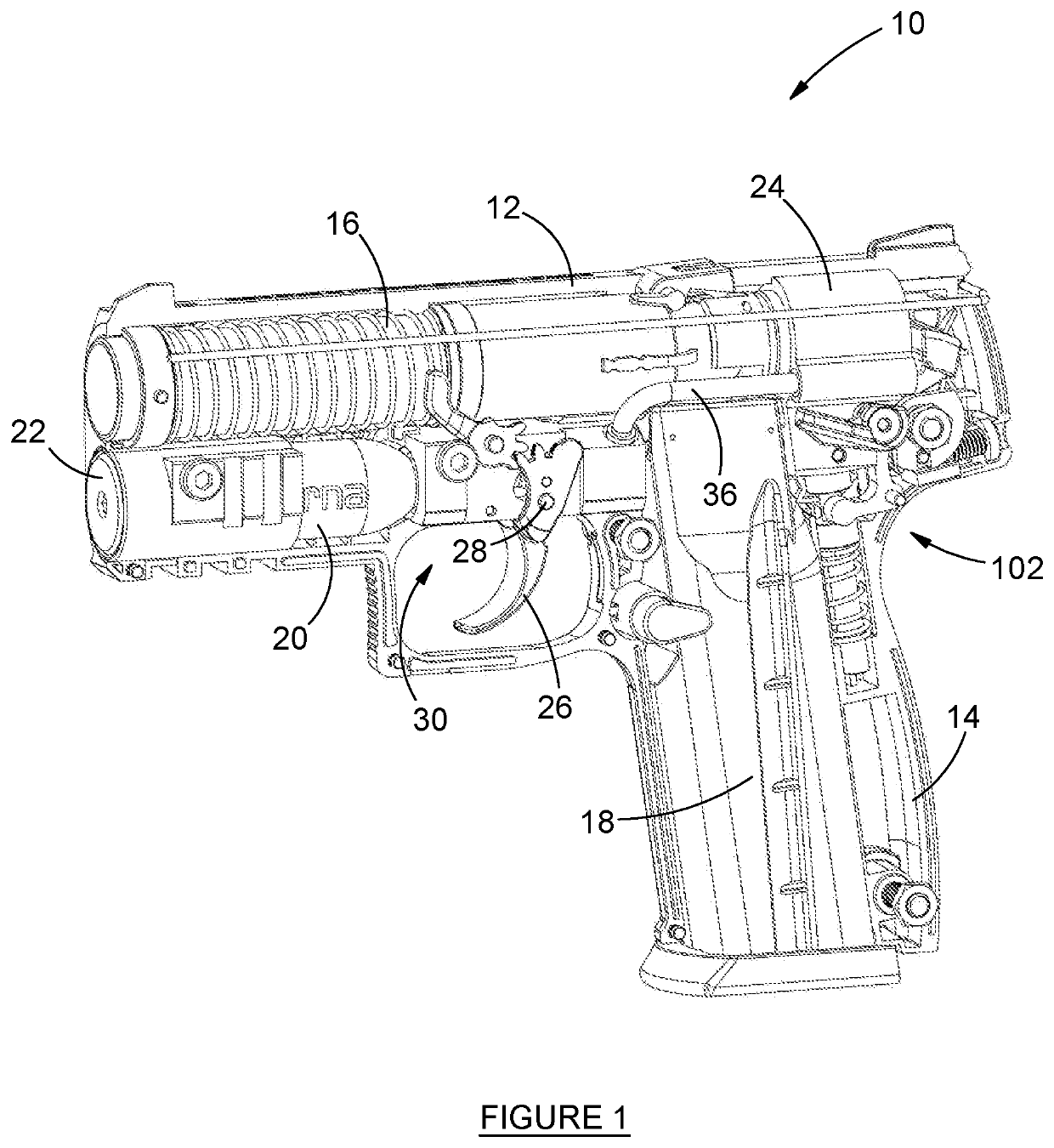
[0108]A less-lethal device, in the form of a less-lethal pistol, is indicated by reference numeral 10 in FIG. 1. The less-lethal device 10 typically comprises a body 12 having a grip portion 14 for handling the device 10 and a barrel 16 through which a projectile (not shown) is propelled in use. A magazine 18 is provided within the grip portion 14 and utilised to house a number of projectiles, and to load projectiles into a breech of the barrel 16. A canister of compressed gas 20 is located within the body 12, and typically, below the barrel 16. The canister 20 is locked in position within the body 12, by a locking cap 22, typically provided with screw-in or a bayonet-type locking mechanism. A release valve 24 is provided to vent a predetermined volume of compressed gas into the barrel 16, thereby to propel the projectile therefrom. The release valve 24 and canister 20 are therefore operatively arranged in fluid-flow communication. The release of gas by the release valve 24 is trigg...


PUM


Abstract

This invention relates to a pneumatic arrangement of a less-lethal device, which pneumatic arrangement comprises a puncture mechanism used for puncturing a sealed mouth of a canister of compressed gas, in use received within a body of the less-lethal device; a pressure sensitive activation assembly used to inhibit the device from propelling a projectile therefrom before a predetermined pressure is reached within a release valve of the device; a release valve assembly for venting compressed gas to a barrel to propel the projectile from the device; and a propelling assembly for adjusting the kinetic force with which a hammer impacts a release valve of the device. The invention also relates to a method of propelling a projectile from a less-lethal device.

Description

INTRODUCTION AND BACKGROUND[0001]This invention relates to a less-lethal device. More particularly, the invention relates to a pneumatic arrangement of a less-lethal device, which pneumatic arrangement comprises a puncture mechanism used for puncturing a sealed mouth of a canister of compressed gas, in use received within a body of the less-lethal device; a pressure sensitive activation assembly used to inhibit the device from propelling a projectile therefrom before a predetermined pressure is reached within a release valve of the device; a release valve assembly for venting compressed gas to a barrel to propel the projectile from the device; and a propelling assembly for adjusting the kinetic force with which a hammer impacts a release valve of the device. The invention also relates to a method of propelling a projectile from a less-lethal device.[0002]The use of lethal force by law enforcement agencies or personnel, private security companies, or even private citizens as defensiv...

Claims


Application Information

Patent Timeline
Patent Type & Authority Applications(United States)
IPC IPC(8): F41B11/62F41B11/723F41B11/73
CPCF41B11/62F41B11/73F41B11/723F41A17/74
Inventor BUYS, ANDRÉ JOHANN
Owner BYRNA TECH INC
Why Eureka
Try Eureka