Apparatus for securing camera to a retail shelving unit

Pending Publication Date: 2021-12-23
TRAX TECH SOLUTIONS
View PDF0 Cites 0 Cited by
  • Summary
  • Abstract
  • Description
  • Claims
  • Application Information

AI Technical Summary

Benefits of technology

The patent text describes a system and method for analyzing images captured in a retail store to determine product options for store execution based on shelf capacity. The system receives a set of images showing a first group of products displayed on a shelving unit and identifies the portion of the shelving unit that is dedicated to the first group of products. It then determines the actual product capacity of the assigned portion of the shelving unit and compares it to the number of products in the set of images. By accessing data about a separate group of products, the system generates suggestions for improving store execution based on the determined product capacity. The technical effect of this patent is an improved ability for retail stores to optimize product placement and maximize sales based on shelf capacity.

Problems solved by technology

Such a monitoring technique, however, may be inefficient and may result in nonuniform compliance among retailers relative to various product-related guidelines.
This technique may also result in significant gaps in compliance, as it does not allow for continuous monitoring of dynamically changing product displays.

Method used


Image

  • Apparatus for securing camera to a retail shelving unit
  • Apparatus for securing camera to a retail shelving unit
  • Apparatus for securing camera to a retail shelving unit

Examples


first embodiment

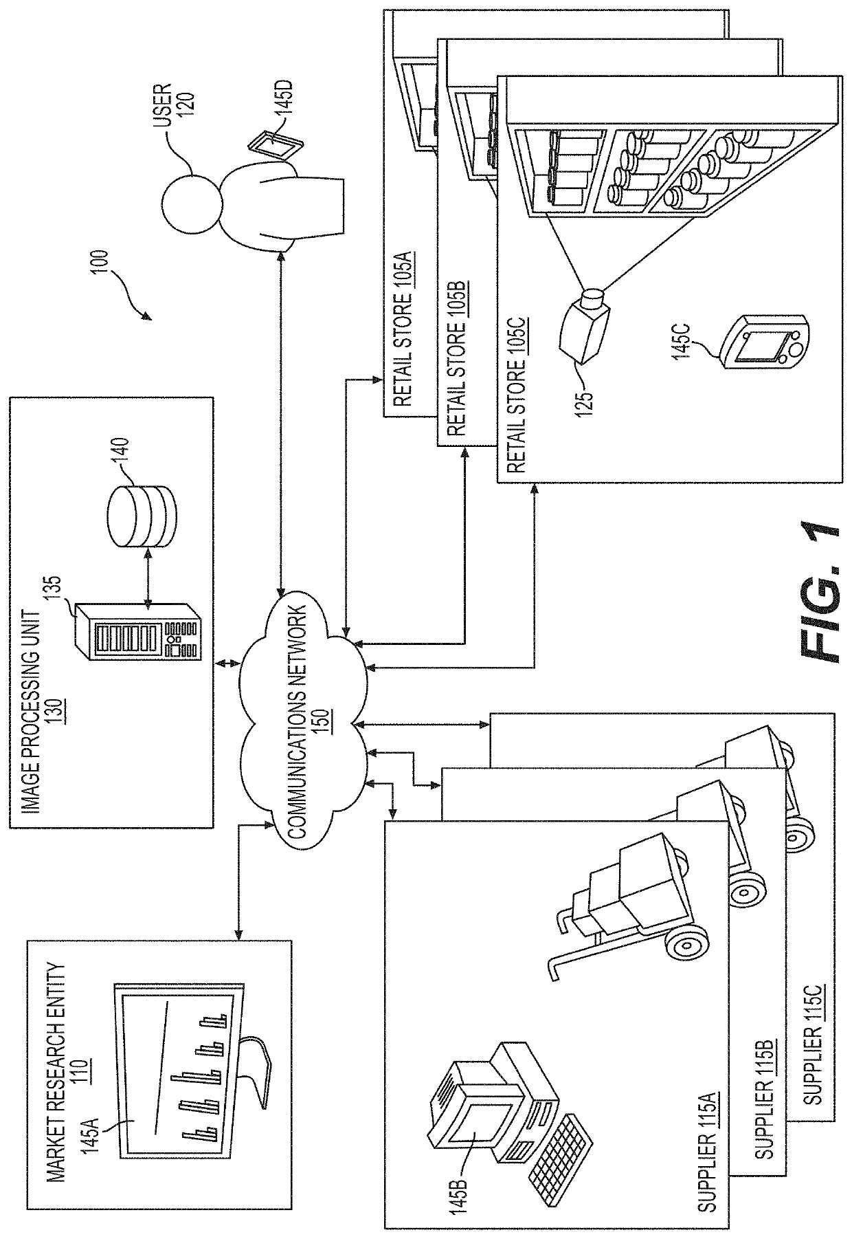
[0147]With reference to FIG. 4B and consistent with the present disclosure, server 135 may receive image data captured by users 120. In a first embodiment, server 135 may receive image data acquired by store employees. In one implementation, a handheld device of a store employee (e.g., capturing device 125D) may display a real-time video stream captured by the image sensor of the handheld device. The real-time video stream may be augmented with markings identifying to the store employee an area-of-interest that needs manual capturing of images. One of the situations in which manual image capture may be desirable may occur where the area-of-interest is outside the fields of view of a plurality of cameras fixedly connected to store shelves in aisle 400. In other situations, manual capturing of images of an area-of-interest may be desirable when a current set of acquired images is out of date (e.g., obsolete in at least one respect) or of poor quality (e.g., lacking focus, obstacles, l...

second embodiment

[0148]In a second embodiment, server 135 may receive image data acquired by crowd sourcing. In one exemplary implementation, server 135 may provide a request to a detected mobile device for an updated image of the area-of-interest in aisle 400. The request may include an incentive (e.g., $2 discount) to user 120 for acquiring the image. In response to the request, user 120 may acquire and transmit an up-to-date image of the area-of-interest. After receiving the image from user 120, server 135 may transmit the accepted incentive or agreed upon reward to user 120. The incentive may comprise a text notification and a redeemable coupon. In some embodiments, the incentive may include a redeemable coupon for a product associated with the area-of-interest. Server 135 may generate image-related data based on aggregation of data from images received from crowd sourcing and from images received from a plurality of cameras fixedly connected to store shelves. Additional details of this embodime...


PUM


Abstract

An apparatus for securing a camera to a retail shelving unit is disclosed. The apparatus may have a pair of opposing securing surfaces for securing the apparatus to a support element of the retail shelving unit. The pair of opposing securing surfaces may form a gap between the pair of opposing securing surfaces. The gap may be configured to accept the support element of the retail shelving unit. The apparatus may also have an arm extending from one of the pair of opposing securing surfaces and having a distal end. The distal end may have a camera support area including a least one opening.

Description

CROSS REFERENCES TO RELATED APPLICATIONS[0001]This application claims the benefit of priority of U.S. Provisional Application No. 62 / 814,339, filed Mar. 6, 2019; U.S. Provisional Application No. 62 / 829,160, filed Apr. 4, 2019; U.S. Provisional Application No. 62 / 872,751, filed Jul. 11, 2019; and U.S. Provisional Application No. 62 / 879,565, filed Jul. 29, 2019. The foregoing applications are incorporated herein by reference in their entirety.BACKGROUNDI. Technical Field[0002]The present disclosure relates generally to systems, methods, and devices for identifying products in retail stores, and more specifically to systems, methods, and devices for capturing, collecting, and automatically analyzing images of products displayed in retail stores for purposes of providing one or more functions associated with the identified products.II. Background Information[0003]Shopping in stores is a prevalent part of modern daily life. Store owners (also known as “retailers”) stock a wide variety of...

Claims


Application Information

Patent Timeline
IPC IPC(8): G08B13/196H04N5/225
CPCG08B13/19632H04N5/2252G08B13/19641G06Q10/087G06Q30/00G06Q10/06313G06Q10/06315G06T7/70G06Q30/0201G06T2207/30232H04N7/181H02J7/0048H02J7/00036H02J7/0013H02J7/0068H02J9/06H04N7/18G06V20/13G06Q10/06312G06Q10/06375G06V20/00G06Q30/0223G06V20/20G06V20/52G06Q30/0639G06Q30/0641G06T7/001G06Q30/0207G06Q30/0242G06Q30/0261G06V30/10G06Q20/208G06Q30/0643G06F18/21H04N23/51H04N23/54H04N23/65
Inventor ADATO, YAIRLISHNER, ITAI
Owner TRAX TECH SOLUTIONS
Why Eureka
Try Eureka