
Method and System for Calibrating a Camera and Localizing Objects Within the Camera Field of View

a camera and camera field technology, applied in the field of security and surveillance systems, can solve the problems of inefficient methods, noisy bounding boxes, and inability to know the height of people exactly

Active Publication Date: 2022-01-27
MOTOROLA SOLUTIONS INC
View PDF10 Cites 7 Cited by
  • Summary
  • Abstract
  • Description
  • Claims
  • Application Information

AI Technical Summary

Benefits of technology

The patent text describes a method and system for accurately determining the position and localizing a person in the field of view of a camera. This is useful for maintaining social distance between persons and ensuring safety. The method involves obtaining the image of the person, determining slant values associated with the person, and using those values to calculate the head and feet image points of the person. The person can then be localized by projecting the head and feet image coordinates to a head and feet plane. The technical effect of this patent is to provide a more precise and accurate way to locate people in a camera's field of view.

Problems solved by technology

In practice, bounding boxes may be noisy, or the human height may not be known exactly.
The methods that require user interaction often involve manually placing objects with calibration patterns in the camera's 108 field of view, measuring distances between points in the camera's field of view, or manually marking up an image with lines; practically, those methods are inefficient.
As should be apparent from this detailed description above, the operations and functions of the electronic computing device are sufficiently complex as to require their implementation on a computer system, and cannot be performed, as a practical matter, in the human mind.
Electronic computing devices such as set forth herein are understood as requiring and providing speed and accuracy and complexity management that are not obtainable by human mental steps, in addition to the inherently digital nature of such operations (e.g., a human mind cannot interface directly with RAM or other digital storage, cannot transmit or receive electronic messages, electronically encoded video, electronically encoded audio, etc., and cannot minimize residuals of the slant model homology equations, among other features and functions set forth herein).

Method used


Image

  • Method and System for Calibrating a Camera and Localizing Objects Within the Camera Field of View
  • Method and System for Calibrating a Camera and Localizing Objects Within the Camera Field of View
  • Method and System for Calibrating a Camera and Localizing Objects Within the Camera Field of View

Examples


Embodiment Construction

[0012]There is a need to calculate distances between objects found in the field of view of a camera, for example to maintain a social distance between persons. There are typically two requirements for being able to determine the position, or localization, of a person, namely camera parameters, such as focal length, camera height, pitch and roll; and precise feet and head image points for the person in the field of view. Typically, not all of these requirements are met, so there is a need for an improved technical method and system to accurately determine unknown camera parameters and localize the persons in the field of view of a camera

[0013]In accordance with one example embodiment, a computer-implemented method of localizing an image of a person captured using a camera, the person in the field of view of a camera, comprising: obtaining the image captured using a camera, the image comprising the person within a bounding box; determining at least one slant value associated with the ...


PUM


Abstract

A computer-implemented method of localizing an image of a person captured using a camera is provided, the person in the field of view of a camera, comprising: obtaining the image captured using a camera, the image comprising the person within a bounding box; determining at least one slant value associated with the person within the bounding box; determining head image coordinates and feet image coordinates for the person using the at least one slant value; and localizing the person by projecting the head image coordinates to a head plane and the feet image coordinates for the person to a ground plane.

Description

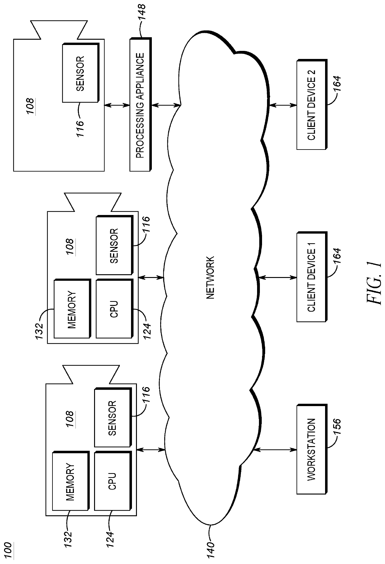
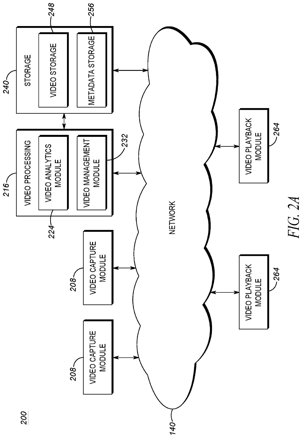
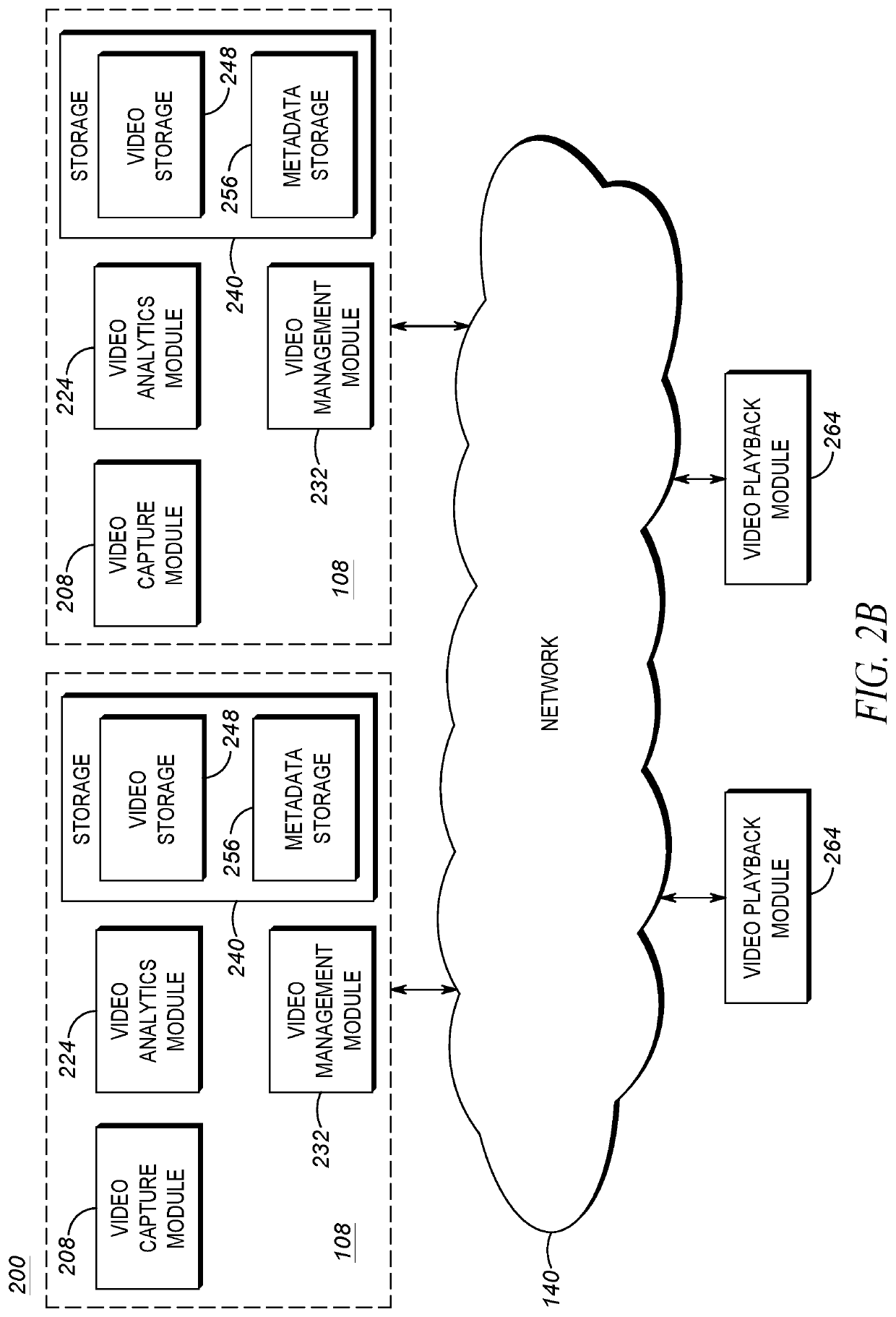
BACKGROUND[0001]Automated security and surveillance systems typically employ video cameras or other image capturing devices or sensors to collect image data such as video or video footage. Images represented by the image data may be displayed for contemporaneous screening by security personnel and / or recorded for later review.BRIEF DESCRIPTION OF THE SEVERAL VIEWS OF THE DRAWINGS[0002]In the accompanying figures similar or the same reference numerals may be repeated to indicate corresponding or analogous elements. These figures, together with the detailed description, below are incorporated in and form part of the specification and serve to further illustrate various embodiments of concepts that include the claimed invention, and to explain various principles and advantages of those embodiments.[0003]FIG. 1 is a block diagram of connected devices of a video capture and playback system according to an example embodiment.[0004]FIG. 2A is a block diagram of a set of operational modules...

Claims


Application Information

Patent Timeline
IPC IPC(8): G06T7/80G01B11/25G06T7/521G01B11/02
CPCG06T7/80G01B11/2518G01B11/2504G01B11/026G06T7/521G06T7/75G06T2207/30196G06T2207/30232G06T2207/30236G06T2207/30244
Inventor LEE, CHIA YINGWANG, YINLIPCHIN, ALEKSEY
Owner MOTOROLA SOLUTIONS INC
Learn More