Magnetically actuated clutch for an additive manufacturing system

a technology of magnetically actuated clutches and additive manufacturing systems, which is applied in the direction of magnetically actuated clutches, applying layer means, mechanical equipment, etc., to achieve the effect of convenient and quick selection, simple yet effective design

Active Publication Date: 2022-02-10
ULTIMAKER BV
View PDF0 Cites 0 Cited by
  • Summary
  • Abstract
  • Description
  • Claims
  • Application Information

AI Technical Summary

Benefits of technology

[0018]The extruder head of the present invention is particularly advantageous as it readily allows for an arbitrary plurality of filament feeders to be connected to and disconnected from a single common drive shaft of the extruder head. Moreover, because each of the plurality of bidirectional magnetic clutches of the extruded head allows for opposite rotations of the drive shaft, it is possible to conveniently ...

Problems solved by technology

However, when the inner shaft rotates and the ball bearing moves outwards, at some point both rin...

Method used


Image

  • Magnetically actuated clutch for an additive manufacturing system
  • Magnetically actuated clutch for an additive manufacturing system
  • Magnetically actuated clutch for an additive manufacturing system

Examples


Embodiment Construction

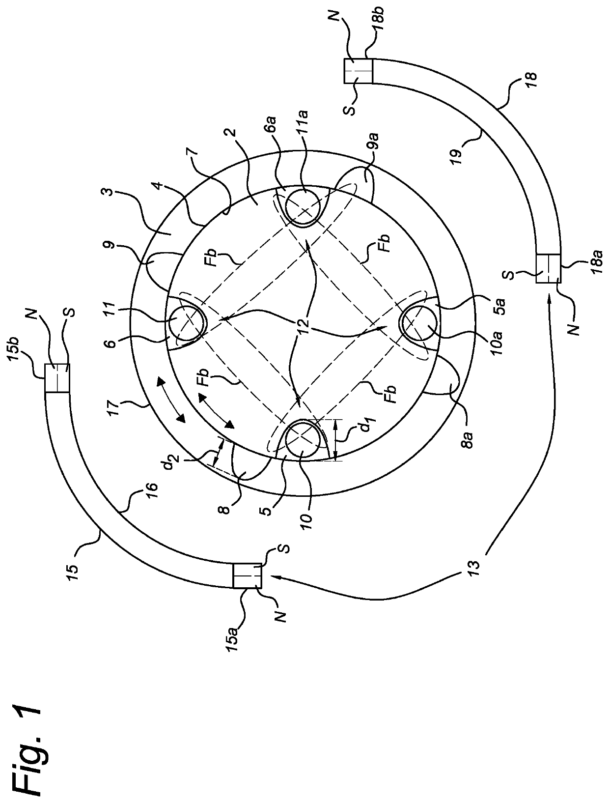
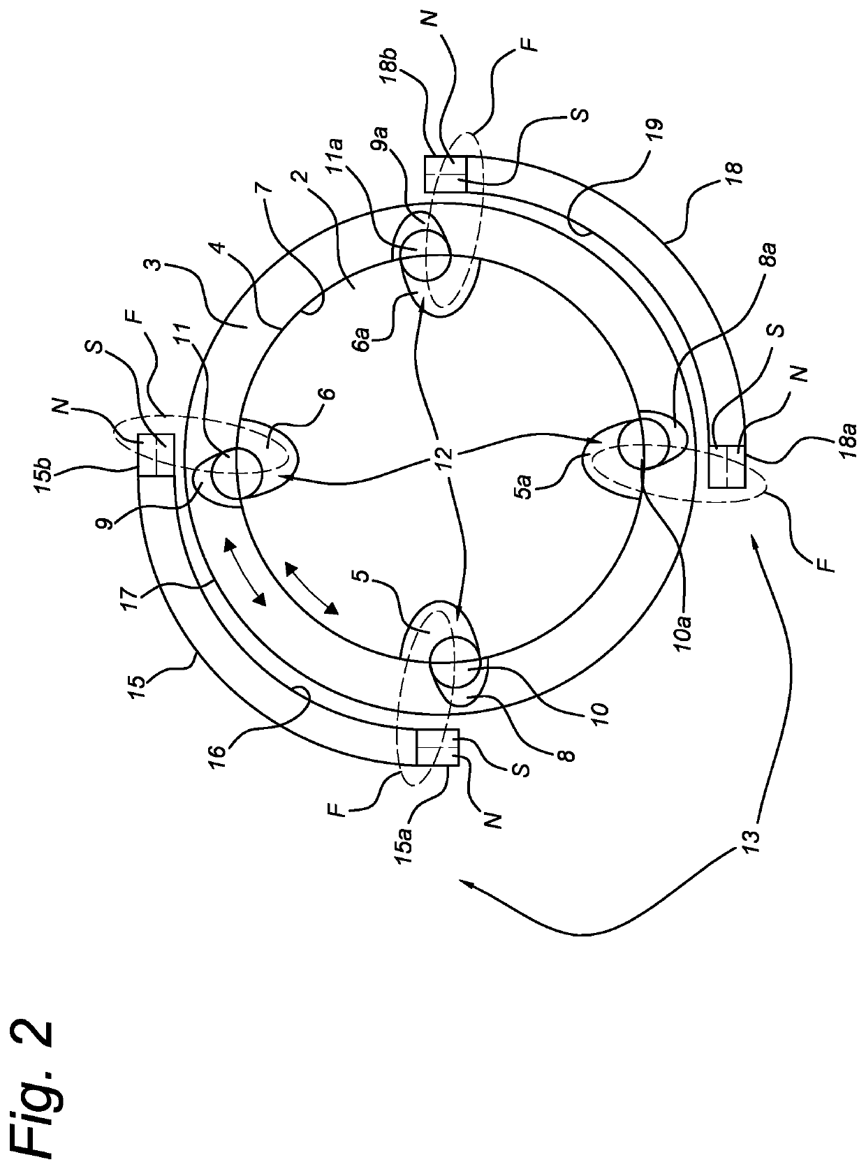
[0030]FIGS. 1 and 2 show cross sections of a disengaged and engaged bidirectional magnetic clutch 1, respectively, for an additive manufacturing system according to an embodiment of the present invention. In the embodiment shown, the bidirectional magnetic clutch comprises a concentric arrangement of an inner drive member 2, e.g. a circular inner drive member 2, and an outer drive member 3, e.g. a circular outer drive member 3, enclosing the inner drive member 2 in the cross section shown, wherein the inner drive member 2 and the outer drive member 3 are rotatable relative to each other.

[0031]The inner drive member 2 comprises at an outer circumferential surface 4 four outward facing recesses 5, 5a, 6, 6a and wherein the outer drive member 3 comprises at an inner circumferential surface 7 four inward facing recesses 8, 8a, 9, 9a. Although not shown, it should be noted that an annular gap may be present between the outer circumferential surface 4 and the inner circumferential surface...


PUM


Abstract

A bidirectional magnetic clutch for an additive manufacturing system, comprising a concentric arrangement of an inner drive member (2) and an outer drive member (3) enclosing the inner drive member (2), the inner and outer drive members (2,3) being rotatable relative to each other. The inner drive member (2) comprises at least two outward facing recesses (5, 6) and the outer drive member (3) comprises at least two inward facing recesses (8,9). Each outward facing recess (5,6) comprises a radially moveable roller member (10,11) of ferromagnetic material. The inner drive member (2) further comprises a magnetic biasing system (12) configured to magnetically bias the roller members (10,11) into the outward facing recesses (5,6). The bidirectional magnetic clutch further comprises a magnet actuator (13) at least partially circumferentially arranged around the outer drive member (3) and configured to maintain an engaged state or disengaged state of the bidirectional magnetic clutch.

Description

FIELD OF THE INVENTION[0001]The present invention relates to a magnetic clutch for an additive manufacturing system, in particular a bidirectional magnetic clutch for an additive manufacturing system. In a further aspect the present invention relates to an extruder head for an additive manufacturing system comprising such a bidirectional magnetic clutch.BACKGROUND ART[0002]U.S. Pat. No. 9,816,571 B1 discloses bidirectional coupler that selectively couples and decouples a driving element to a driven element. The coupler includes an outer shaft having an outer shaft slot and an inner shaft having an inner shaft slot, where the inner and outer shafts are configured to rotate independently of each other. The coupler also includes a ball bearing provided within the inner shaft slot and having a size so that when the ball bearing is located at a center portion of the inner shaft slot it does not interfere with rotation of the outer shaft, where the ball bearing is held in that location by...

Claims


Application Information

Patent Timeline
IPC IPC(8): F16D27/00F16D27/14B29C64/209B33Y30/00
CPCF16D27/004F16D27/14F16D2200/0008B33Y30/00B29C64/209F16D27/01F16D27/102F16D2041/0646F16D41/088F16D2027/008
Inventor HUITEMA, ROBERTVERSTEEGH, JOHAN ANDREASVAN DER ZALM, ERIKNEUT, MATTHIJSVAN BEEK, TEUNELSERMAN, MARTIJN
Owner ULTIMAKER BV
Why Eureka
Try Eureka