

Bulk handling feature
a technology for handling features and components, applied in the field of bulk handling features, can solve the problems of not good in the bulk handling aspect, difficult handling of components in bulk, etc., and achieve the effect of greatly reducing or minimizing the risk of entanglement of the elongated members of several components, and reducing the risk of damage to the elongated members due to the weight of a large number of other components stacked in bulk
- Summary
- Abstract
- Description
- Claims
- Application Information
AI Technical Summary
Benefits of technology
Problems solved by technology
Method used
Image

Examples
Embodiment Construction
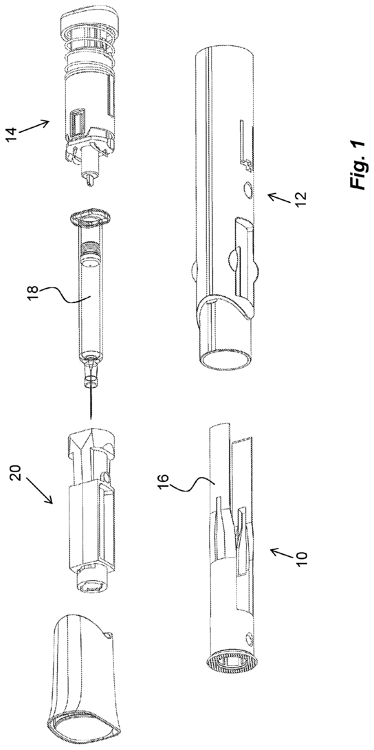
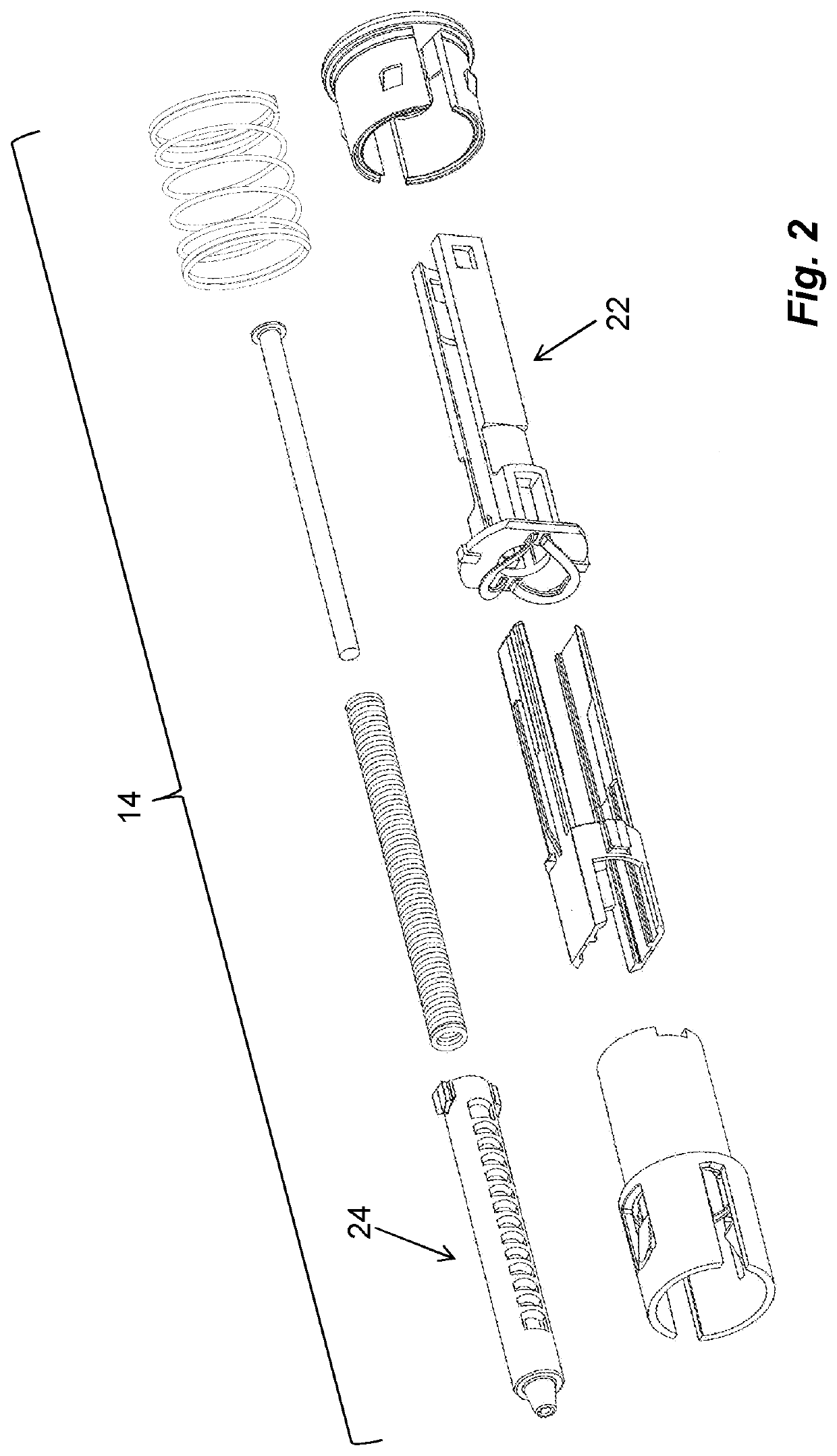
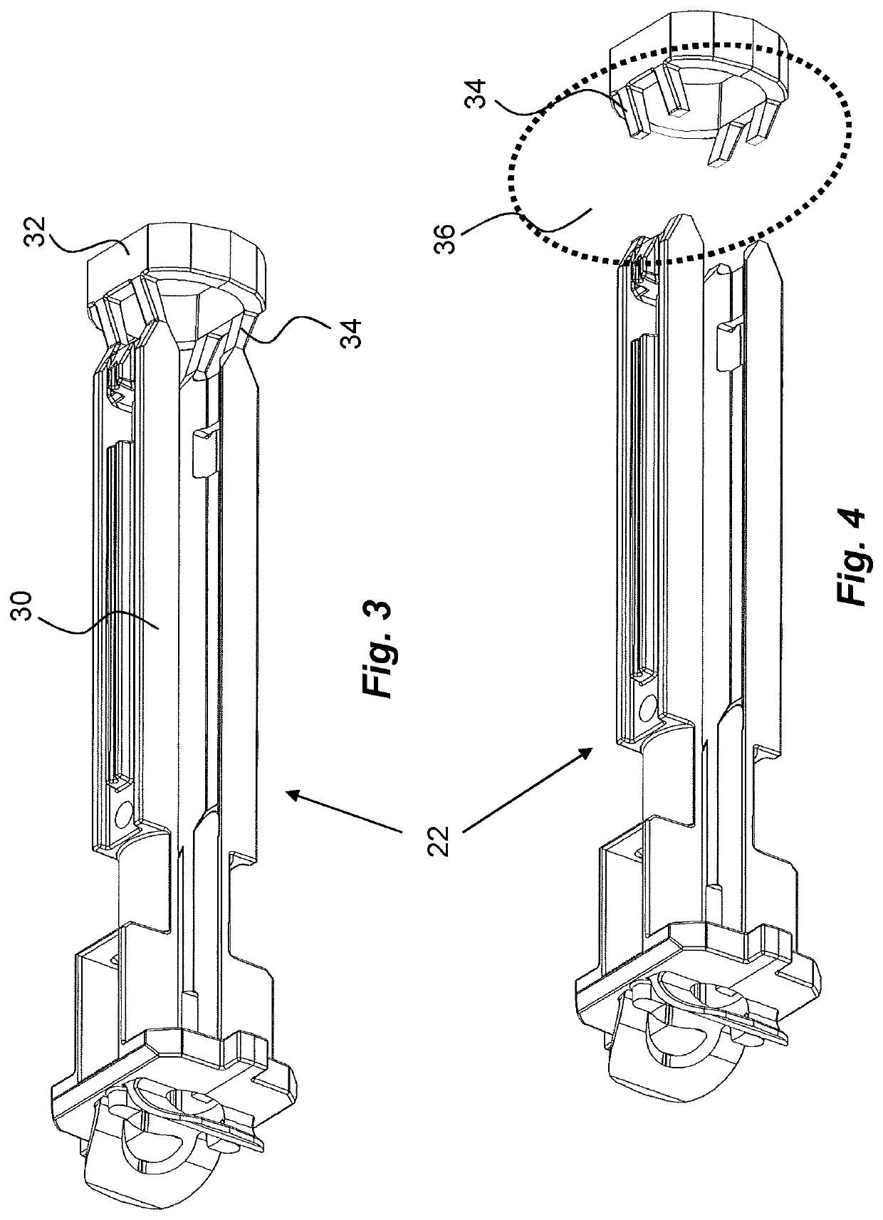
[0019]FIG. 3 shows one example of a component that is difficult to handle in bulk. In the shown example, the component is a plunger rod holder 22 that is used in a power pack 14 of a medicament delivery device. The plunger rod holder 22 is arranged with two arms 30 extending in a distal direction, wherein the arms are designed to run on opposite sides of a plunger rod 24.
[0020]When the component 22 is molded, a connecting support element 32 is integrated with the free ends of the arms 30. This will prevent the arms 30 from entangling in other components when placed together in bulk. As seen in FIGS. 3 and 4, the support element 32 is provided with thinner areas 34 adjacent the ends of the arms 30. When the components 22 have been sorted by an appropriate machine and are ready for assembly, the support element 32 will be detached from the arms 30, as seen in FIG. 4. This may be done by different techniques and equipment 36 such as blade cutting, sawing, or heating by laser for instan...
PUM
 Abstract
Description
Claims
Application Information