
Tool assembly for mounting of a dental prosthesis and method of mounting

a technology for dental prostheses and tools, applied in dentistry, dental science, dental surgery, etc., can solve the problems of difficult or impossible to easily access the head of the implant screw, and the inability to easily manipulate tools, etc., to reduce or minimize the risk of a tool part dislodging or free falling. , the effect of easy manipulation

Pending Publication Date: 2022-03-17
JADE FINANCE S A R L
View PDF0 Cites 0 Cited by
  • Summary
  • Abstract
  • Description
  • Claims
  • Application Information

AI Technical Summary

Benefits of technology

The disclosure provides mounting tools and techniques for easy manipulation by dentists to securely fix elements such as abutments, reducing the risk of the tool parts dislodging or falling. The unique design allows for better control and ease of use in tight spaces, making the process easier and more efficient for dentists. Additionally, the abutment used in the tool assembly does not require a cut-out portion for the tool, making it less complex and cheaper. Overall, the tool assembly and techniques provide a more reliable and secure means to fix dental implants.

Problems solved by technology

In some configurations, it may be useful to provide an inclined abutment (angulated relative to the implant screw and thereby the implant), but this may be problematical since it makes it difficult or impossible to easily access the head of the implant screw with the usual (substantially straight) tool through the angulated abutment bore.
A problem is that, with known mounting / fixing tools and techniques, the tools are not such as to be easily manipulated by a dentist in the dental surgery, making fixing of elements such as abutments securely in place more difficult.
Further, as the tool parts in question are of relatively small dimensions (e.g. up to 30 mm), the difficulty of manipulation raises the risk of the dentist's grip of a tool part being lost, of a tool part dislodging or falling, and even of a tool part being swallowed or even inhaled by a patient being treated.

Method used


Image

  • Tool assembly for mounting of a dental prosthesis and method of mounting
  • Tool assembly for mounting of a dental prosthesis and method of mounting
  • Tool assembly for mounting of a dental prosthesis and method of mounting

Examples


Embodiment Construction

[0043]In the following, like reference numerals denote like parts, and any element, design feature or method step of any embodiment may be used in combination with an element, design feature or method step of any other embodiment unless stated otherwise herein.

[0044]Throughout the description and claims of this specification, the singular encompasses the plural unless the context otherwise requires. In particular, where the indefinite article is used, the specification is to be understood as contemplating plurality as well as singularity, unless the context requires otherwise.

[0045]Features, integers, characteristics, compounds or groups described in conjunction with a particular aspect, embodiment or example of the disclosure are to be understood to be applicable to any other aspect, embodiment or example described herein unless incompatible therewith.

[0046]Throughout the description and claims of this specification, the terms “aperture” and “bore” include without limitation any ap...


PUM


Abstract

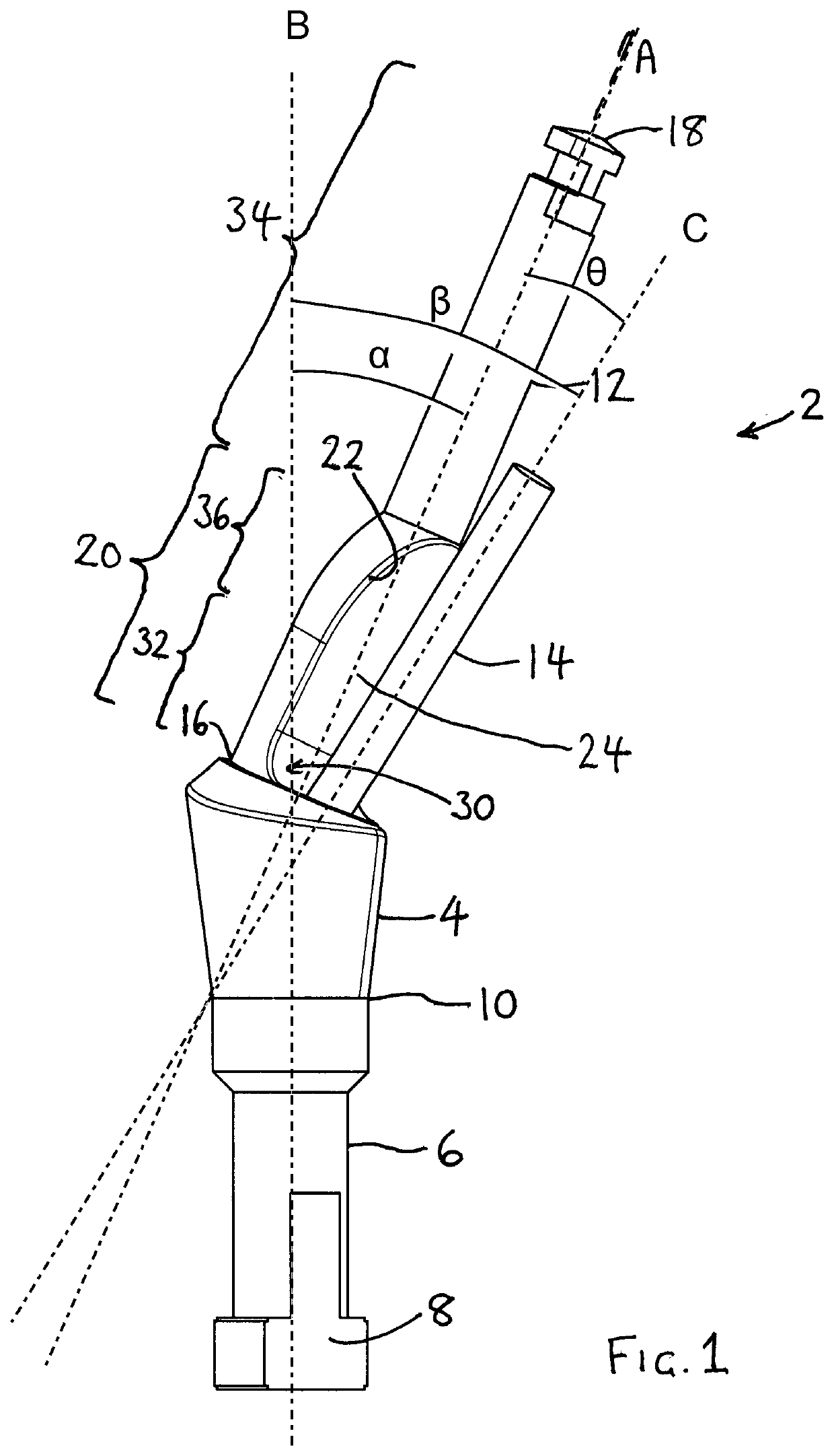
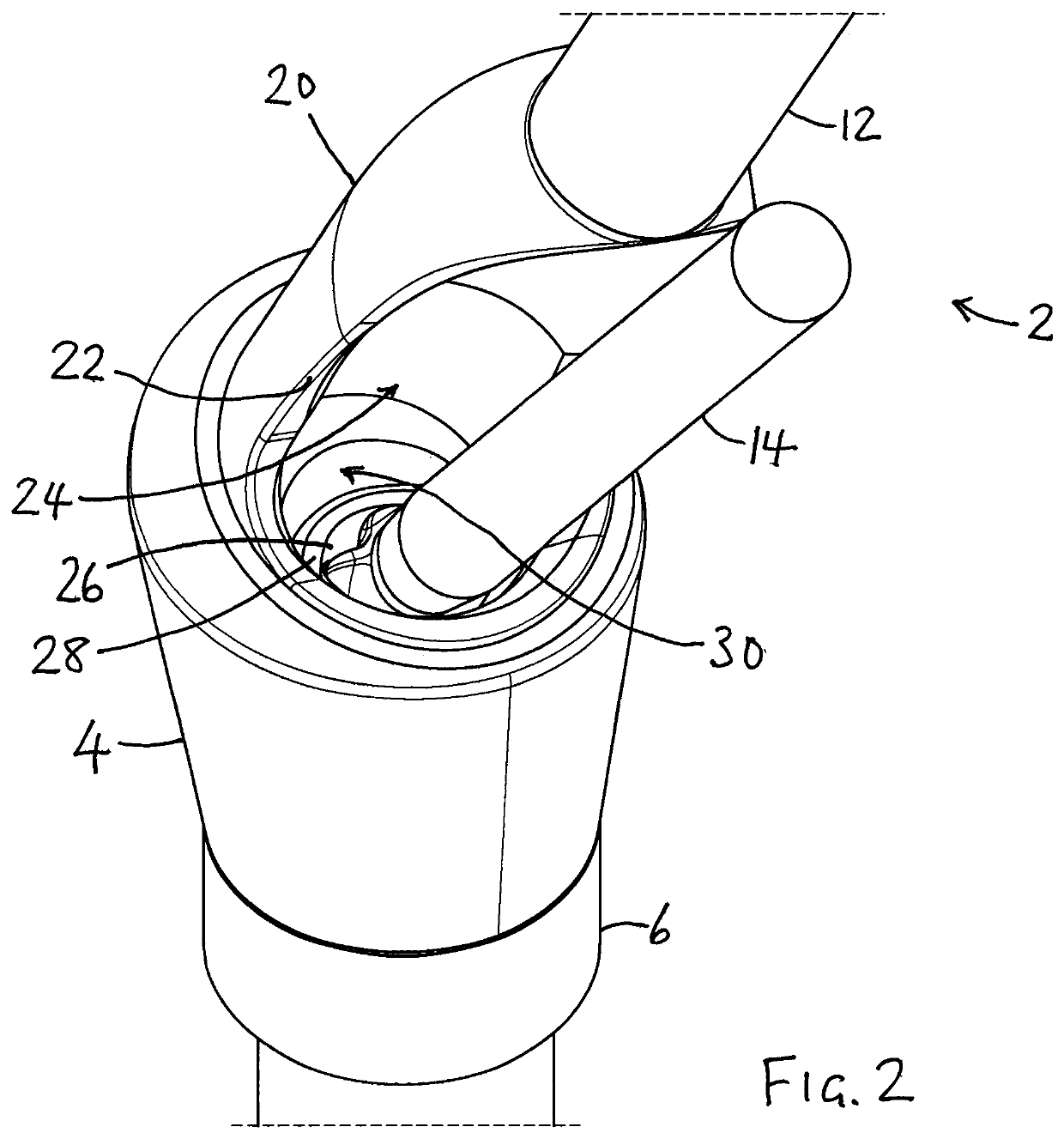
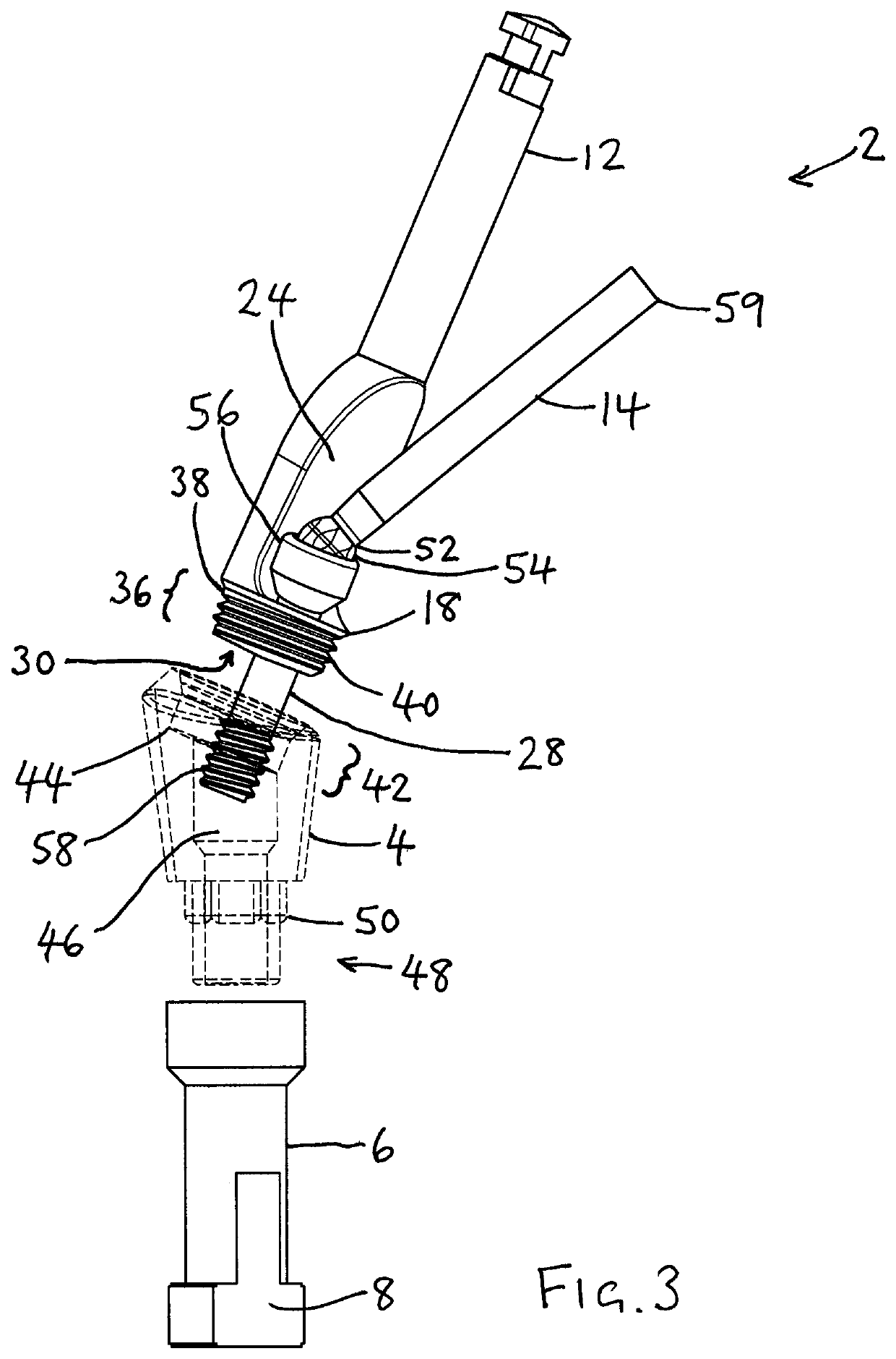
A tool assembly for mounting a dental abutment includes a first tool, the first tool having an axis of elongation, a first end configured to engage, in use, the abutment, and a second end, where a first portion of the first tool at or near the first end has a peripheral wall and, opposite the wall, a first opening extending along all or part of the first portion, a second opening open in an axial direction is disposed at the first end, the tool assembly further including a second tool configured to releasably engage a fixing element, where a contiguous space is defined between the first opening and the second opening whereby, in use, the fixing element, or the fixing element attached to the second tool, may pass through the first opening and the second opening to permit secure fixing of the abutment to an implant or frame using the second tool.

Description

TECHNICAL FIELD[0001]The present disclosure generally relates to techniques for the mounting of a dental prosthesis such as a crown, bridge or denture. The disclosure more particularly relates to an improved tool assembly for mounting an abutment and to method of mounting an abutment.BACKGROUND[0002]Dental implants are often used when a patient requires a prosthetic device to hold one or more artificial teeth in place. Such implants are typically securely mounted to the jawbone, e.g. by surgical screws or other hygienic fixing means; and then, over a period, typically months, the bone and other tissue are permitted to grow around the implant.[0003]A metal abutment may subsequently be securely fixed to the implant or a base thereon, and then a dental prosthesis such as a tooth crown, dental bridge or dental construction e.g. manufactured using 3D printing, may subsequently be securely fixed onto the abutment.[0004]Typically, the metal abutment is fixed to the implant or a base thereo...

Claims


Application Information

Patent Timeline
Patent Type & Authority Applications(United States)
IPC IPC(8): A61C8/00
CPCA61C8/0089A61C8/0068A61C8/0066A61C8/0063A61C8/0062A61C8/005A61C8/0087A61C8/0069
Inventor HORNBECK, JACQUES
Owner JADE FINANCE S A R L
Learn More