Adaptive coverage optimization in single-frequency networks (SFN)

Pending Publication Date: 2022-03-24
ROHDE & SCHWARZ GMBH & CO KG
View PDF4 Cites 0 Cited by
  • Summary
  • Abstract
  • Description
  • Claims
  • Application Information

AI Technical Summary

Benefits of technology

[0048]Advantageously, measuring the SFN reception of the signals by the one or more field probes results in a reliable coverage monitoring in the field.
[0049]Advantageously, measuring the SFN reception of the signals tr

Problems solved by technology

Areas of bad reception in an SFN are difficult to identify in field.
If areas of bad reception can be identified, it is laborious for network operators to tune the transmission parameters for

Method used


Image

  • Adaptive coverage optimization in single-frequency networks (SFN)
  • Adaptive coverage optimization in single-frequency networks (SFN)
  • Adaptive coverage optimization in single-frequency networks (SFN)

Examples


Example

[0057]These figures are to be regarded as being schematic representations and elements illustrated therein are not necessarily shown to scale. Rather, the various elements are represented such that their function and general purpose become apparent to a person skilled in the art.

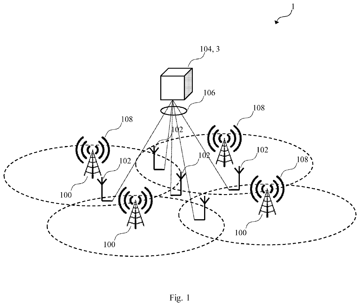
[0058]FIG. 1 shows an SFN system 1 according to a third aspect of the present disclosure.

[0059]The SFN system 1 comprises at least two independently controlled SFN transmitters 100 being arranged to simultaneously transmit / broadcast a same signal 108 over a same frequency channel. More precisely, FIG. 1 illustrates four independently controlled SFN transmitters 100 having individual coverage areas indicated by dashed circles.

[0060]The term “independently controlled” as used herein may refer to “being operable based on transmitter-specific SFN transmission parameters”. For example, SFN transmitters 100 may be operated using different output powers.

[0061]The SFN system 1 further comprises one or more field pro...


PUM


Abstract

A single-frequency network, SFN, system comprises: at least two independently controlled SFN transmitters; a network entity being arranged for computing optimized SFN transmission parameters specifically for each of the at least two SFN transmitters; and one or more field probes arranged in the SFN and connected to the network entity via a network communication channel. The one or more field probes are arranged for measuring, preferably continuously, an SFN reception of signals transmitted by the at least two independently controlled SFN transmitters, producing field measurement data, and supplying the field measurement data to the network entity. The network entity is arranged for automatically calculating, as a function of the supplied field measurement data, at least one type of SFN transmission parameter specifically optimized for each of the at least two independently controlled SFN transmitters, in order to optimize the SFN reception of the signals transmitted by the at least two independently controlled SFN transmitters, and supplying the transmitter-specifically optimized SFN transmission parameters to each of the at least two independently controlled SFN transmitters.

Description

PRIORITY[0001]This application claims priority of European Patent Application EP 20 197 987.9 filed on Sep. 24, 2020, which is incorporated by reference herewith.FIELD OF THE INVENTION[0002]The present application relates to single-frequency networks, and in particular to a method for adaptive optimization of reception / coverage within an SFN, as well as to a corresponding network entity and a corresponding SFN system.BACKGROUND OF THE INVENTION[0003]In single-frequency networks, a plurality of transmitters simultaneously transmits / broadcasts a same signal over a same frequency channel. Areas of bad reception in an SFN are difficult to identify in field.[0004]For example, EP 2 878 156 B1 discloses identifying coverage holes in cellular radio communications using measurements associated with handovers between different radio access technologies (i.e., inter-RAT handovers). U.S. Pat. No. 5,465,390 A discloses determining geographic locations of the transmitters and of their technical c...

Claims


Application Information

Patent Timeline
IPC IPC(8): H04W24/02H04W24/08
CPCH04W24/02H04W24/08H04W16/18H04W52/327H04W52/143H04B17/309H04W52/42
Inventor SINNHUBER, JOHANNESJANNER, THOMAS
Owner ROHDE & SCHWARZ GMBH & CO KG
Why Eureka
Try Eureka