Delivery device of electric components

A technology for conveying devices and electrical components, which is applied in the direction of electrical components, electrical components, etc., and can solve problems such as component jamming and damage

Inactive Publication Date: 2006-07-26
SIEMENS AG
View PDF1 Cites 2 Cited by
  • Summary
  • Abstract
  • Description
  • Claims
  • Application Information

AI Technical Summary

Problems solved by technology

Components can then, for example, get stuck in the transmission of the transfer wheel and cause damage there

Method used


Image

  • Delivery device of electric components
  • Delivery device of electric components
  • Delivery device of electric components

Examples


Embodiment Construction

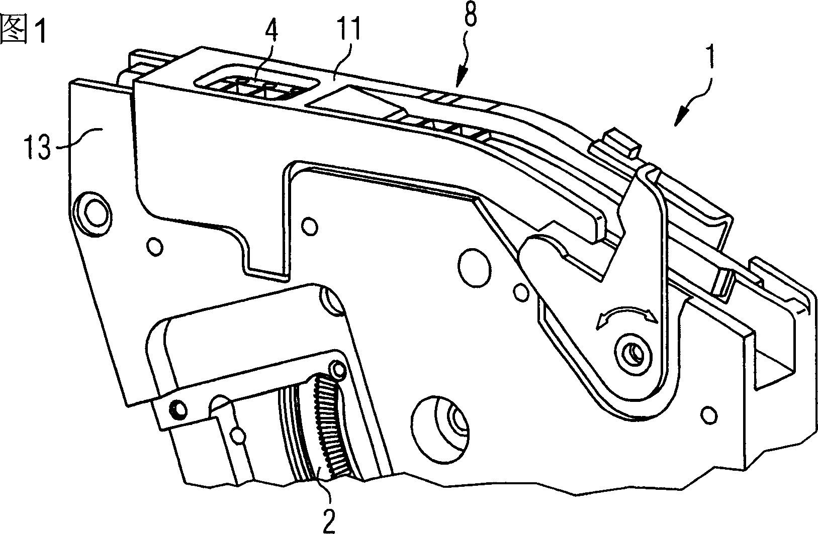
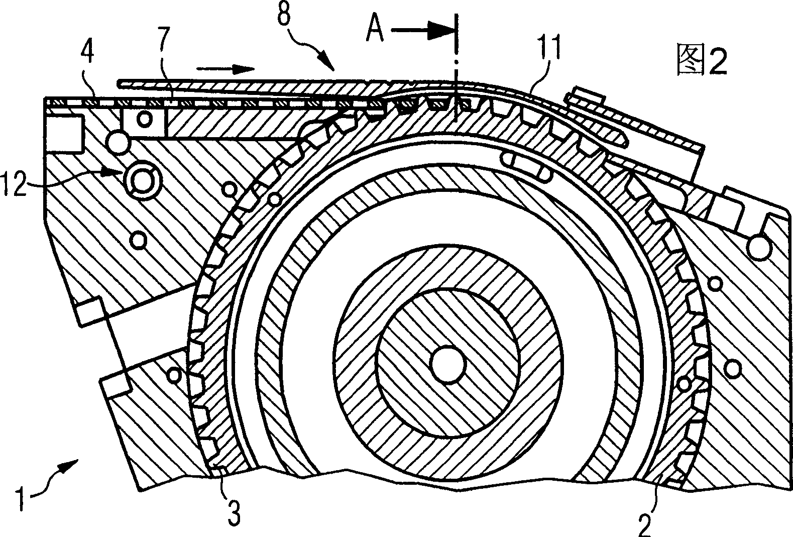
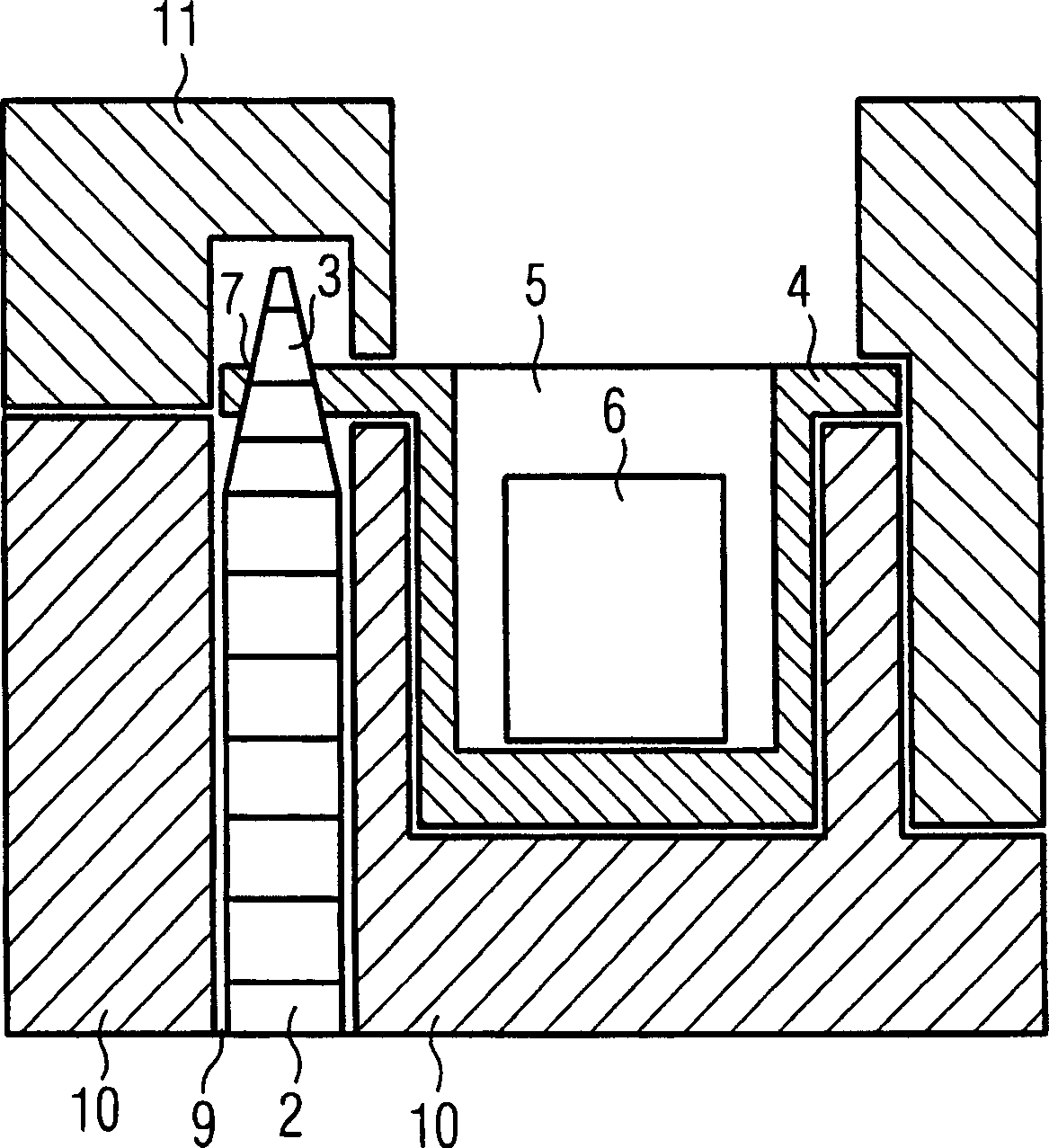
[0012] Figures 1 and 2 show perspective and cross-sectional views of an embodiment of a delivery device according to the invention. image 3 A schematic cross-section along section line A in FIG. 2 is shown. The conveying device 1 has a conveying wheel 2, on the outer circumference of which pins 3 extend radially. The component conveyor belt 4 , in which the electrical components 6 are accommodated in the pocket-like recess 5 , has laterally perforations 7 into which the pins 3 of the conveyor wheels 2 can engage. The components 6 are conveyed in the conveying direction (indicated by the arrow in FIG. 2 ) to the pick-up position 8 of the conveying device 1 by driving the conveying wheel 2 in rotation by means of a transmission not shown. At the pick-up position 8 , the electrical component 6 is picked up, for example, by a mounting head of an automatic assembly machine. In order to protect the components 6 , the component conveyor belt 4 usually has a protective film covering...


PUM


Abstract

The invention relates to a conveying device (1) which is particularly used for the electric element (6) and comprises a conveying wheel (2) provided with a pin (3) on the periphery of the conveying wheel; the pin is embedded into the corresponding perforation (7) of a conveying belt (4) so that the conveying belt (4) is conveyed along the conveying direction and the conveying wheel is extended to a gap (9); the gap is composed of two wall segments (10) extended along the conveying direction of the conveying device (1); the conveying device is provided with a cover piece (11) used for covering the gap (9).

Description

technical field [0001] The invention relates in particular to a conveying device for conveying component conveyor belts loaded with electrical components. Background technique [0002] Patent document DE 10020748 discloses such a delivery device. Accordingly, the conveying device comprises a transfer wheel having pins on its outer periphery which engage in corresponding perforations of the component conveyor belt carrying the components in pocket-shaped recesses thereof. Through the rotation of the transport wheel, the components are gradually transported in this way to the pick-up position, where they are picked up, for example, by the assembly head. The conveyor wheels generally run in a gap formed by two wall sections of the conveyor device extending in the conveying direction of the conveyor belt. Since the transfer wheels are mostly located close to the pick-up position of the conveyor, it is always the case that exposed components inside the recessed part of the comp...

Claims


Application Information

Patent Timeline
IPC IPC(8): H05K13/02H05K13/04
CPCH05K13/0417H05K13/0419
Inventor T·利贝克A·林特纳
Owner SIEMENS AG
Why Eureka
Try Eureka