
Camera module

a technology of camera module and lens barrel, which is applied in the field of camera module, can solve the problems of difficulty in ensuring sufficient coupling force (or binding force) between the press-fit ring and the lens barrel

Pending Publication Date: 2022-04-28
SAMSUNG ELECTRO MECHANICS CO LTD
View PDF2 Cites 1 Cited by
  • Summary
  • Abstract
  • Description
  • Claims
  • Application Information

AI Technical Summary

Benefits of technology

The patent text describes a feature in a camera lens system where the distance between the rearmost lens and the second accommodation space decreases from the object side to the imaging plane. This results in improved optical performance and image quality.

Problems solved by technology

However, in an example where the lenses are fixed through the press-fit ring, it may be difficult to secure sufficient coupling force (or a binding force) between the press-fit ring and the lens barrel.

Method used


Image

  • Camera module
  • Camera module
  • Camera module

Examples


Embodiment Construction

[0036]The following detailed description is provided to assist the reader in gaining a comprehensive understanding of the methods, apparatuses, and / or systems described herein. However, various changes, modifications, and equivalents of the methods, apparatuses, and / or systems described herein will be apparent after an understanding of the disclosure of this application. For example, the sequences of operations described herein are merely examples, and are not limited to those set forth herein, but may be changed as will be apparent after an understanding of the disclosure of this application, with the exception of operations necessarily occurring in a certain order. Also, descriptions of features that are known after an understanding of the disclosure of this application may be omitted for increased clarity and conciseness, noting that omissions of features and their descriptions are also not intended to be admissions of their general knowledge.

[0037]The features described herein m...


PUM


Abstract

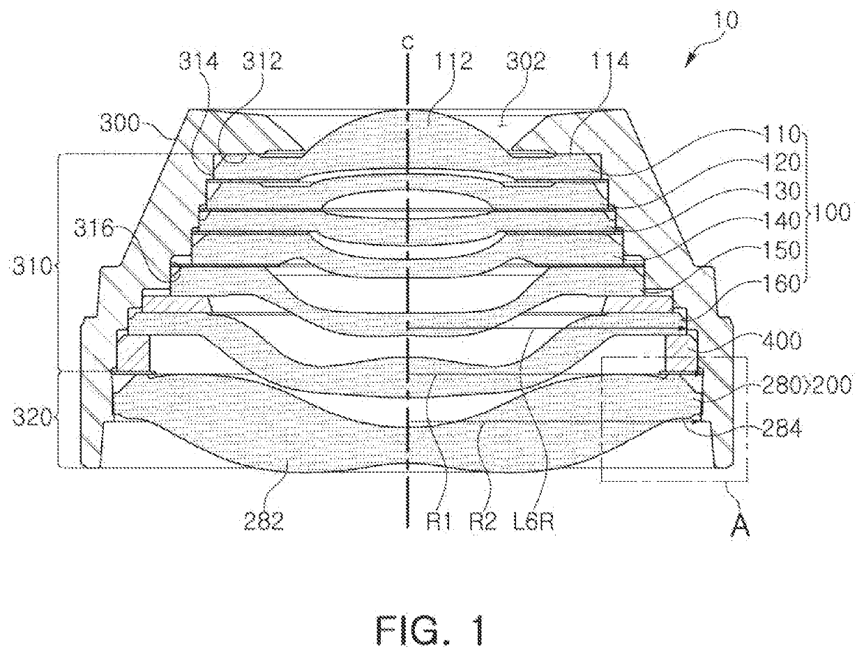
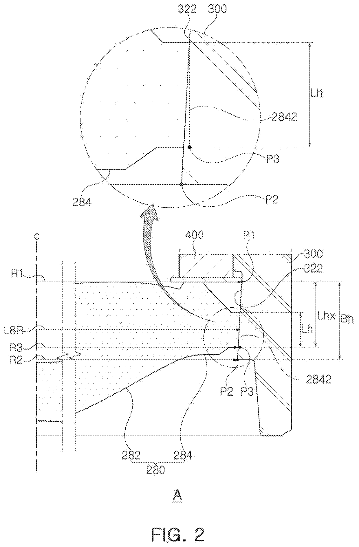
A camera module is provided. The camera module includes a first lens group including a foremost lens disposed closest to an object; a second lens group including a rearmost lens disposed closest to an imaging plane; and a lens barrel in which a first accommodation space and a second accommodating space are formed, the first accommodation space configured to accommodate the first lens group therein, and the second accommodating space configured to accommodate the second lens group therein. The second accommodation space may become narrower from an object side toward the imaging plane.

Description

CROSS-REFERENCE TO RELATED APPLICATION(S)[0001]This application claims the benefit under 35 USC 119(a) of Korean Patent Application No. 10-2020-0141518 filed on Oct. 28, 2020 in the Korean Intellectual Property Office, the entire disclosure of which is incorporated herein by reference, for all purposes.BACKGROUND1. Field[0002]The following description relates to a camera module.2. Description of Related Art[0003]A camera module includes lenses. In an example, a high-resolution camera module includes four or more lenses. The lenses are disposed in a lens barrel. In an example, first to fourth lenses may be sequentially disposed from an object side to an image side of the lens barrel. The camera module includes a component that prevents separation of the lens disposed in the lens barrel. In an example, the camera module may include a press-fit ring or a similar-type ring that fixes the lens to the lens barrel. The press-fit ring may be fixed to the lens barrel by a press-fitting proce...

Claims


Application Information

Patent Timeline
Patent Type & Authority Applications(United States)
IPC IPC(8): G03B17/12G02B7/02
CPCG03B17/12G02B7/025G02B7/021G02B7/022G02B13/0045H04N23/57H04N23/55
Inventor LEE, JONG GISON, JU HWAAHN, JONG HO
Owner SAMSUNG ELECTRO MECHANICS CO LTD
Learn More