Mixer system for a liquid chromatography system

a liquid chromatography and mixing system technology, applied in the direction of separation processes, instruments, measurement devices, etc., can solve the problems of compact design and generally very high installation space requirements, and achieve the effect of reducing installation space, minimizing assembly effort, and low overall heigh

Pending Publication Date: 2022-05-05
BURKERT WERKE
View PDF0 Cites 0 Cited by
  • Summary
  • Abstract
  • Description
  • Claims
  • Application Information

AI Technical Summary

Benefits of technology

[0010]Preferably, the valve is oriented perpendicularly to the plane in which the adapter extends. This allows the corresponding valve to be mounted in a flat manner against a side face of the adapter, thereby minimizing the assembly effort.
[0011]The valve preferably extends parallel to an adjacent adapter of an adjacent valve to achieve a compact design, so that as little clearance as possible remains between the adapter and the valve.
[0012]With regard to a low overall height, it may be provided that the valve has the shape of a flat cuboid and that the plane in which the cuboid extends is aligned perpendicularly to the plane in which the adjacent adapter extends. In other words, the valves are arranged in a tilted manner, which reduces the installation space required in one direction. With a view to a modular structure, each adapter and each valve are attached in a detachable manner, i.e. the adapters are detachably attached to the mixer block, and the valves are detachably attached to the corresponding adapter.
[0013]Preferably, the mixer block and / or the adapters are injection molded so that the components can be manufactured in high quantities at low cost but with high precision.

Problems solved by technology

This results in a generally very high installation space requirement.
This results in a particularly compact design.

Method used


Image

  • Mixer system for a liquid chromatography system
  • Mixer system for a liquid chromatography system
  • Mixer system for a liquid chromatography system

Examples


first embodiment

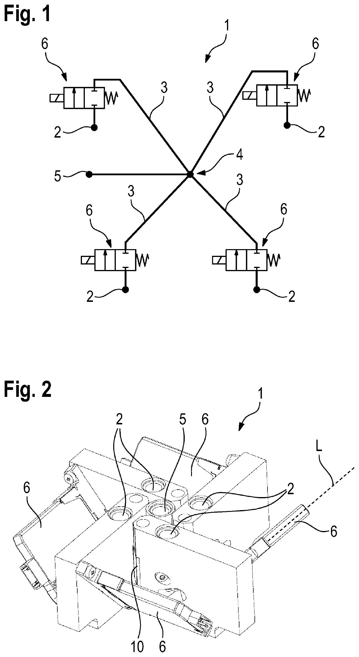
[0029]FIGS. 2 to 6b show the mixer system 1. The mixing chamber 4 is formed in a mixer block 10, which is also provided with the fluid outlet 5.

[0030]The mixer block 10 is designed here in the shape of a cuboid or a cube, wherein, for ease of understanding, reference is made hereafter to the reference system used in FIG. 2, in which the mixer block 10 rests with its underside on a base, the fluid outlet extends vertically upwards from its upper side, and the mixer block has a plurality of side faces 12, which respectively extend in vertical planes.

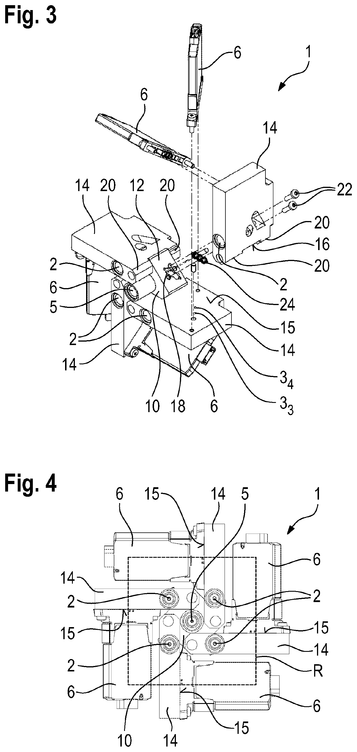
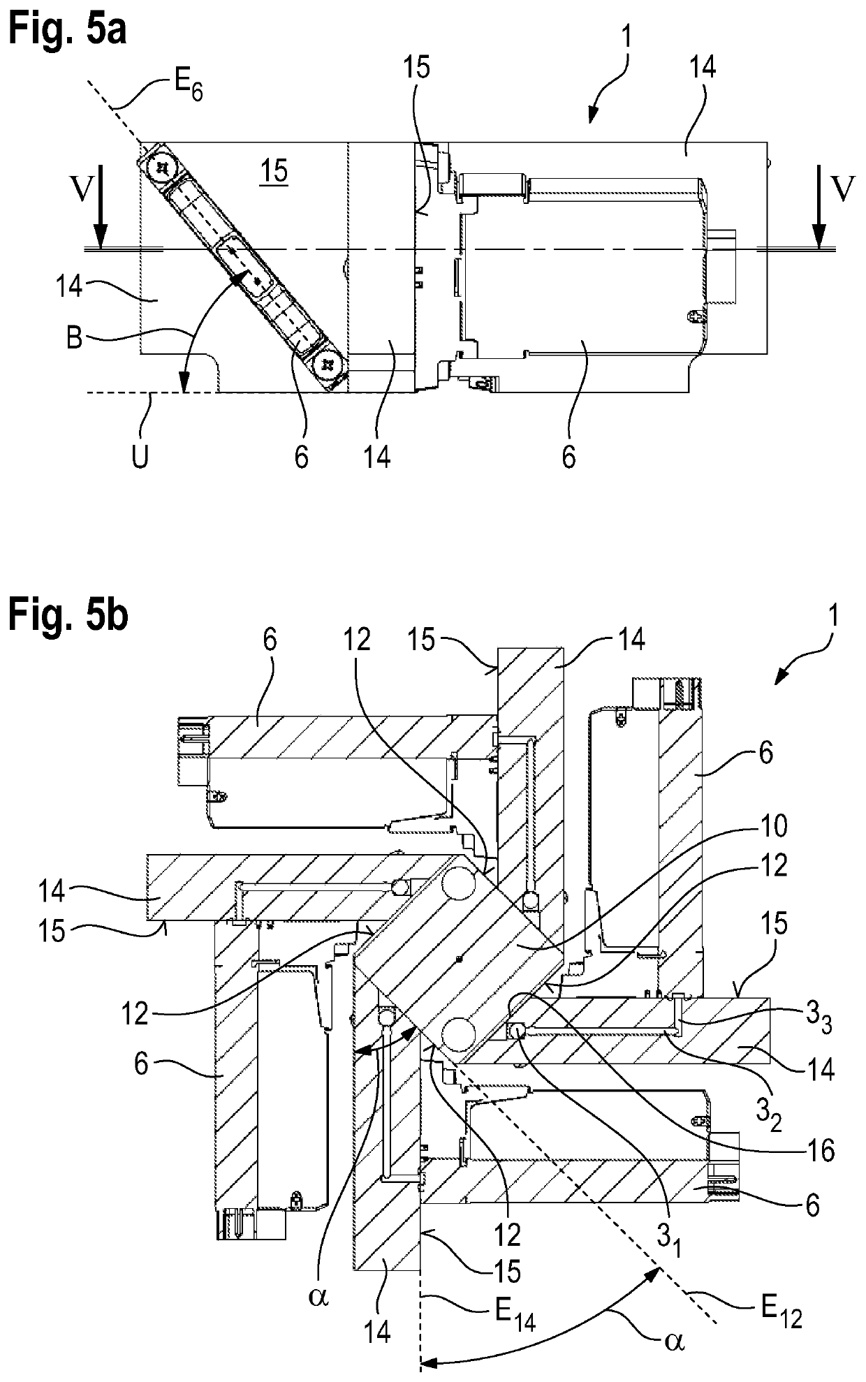
[0031]In the example embodiment shown, the mixer block has a square shape in a horizontal cross-section (see FIGS. 5b and 6b).

[0032]The valves 6 are not directly attached to the mixer block 10; rather, each valve 6 is attached to an adapter 14, which in turn is attached to the mixer block 10.

[0033]In the first embodiment, each adapter 14 is provided with a fluid inlet 2 (see FIGS. 2, 3, 4) from which a vertical section 31 initially extends...

second embodiment

[0054]FIGS. 7 to 9 show the mixer system. The same reference numerals are used for the components known from the previous embodiment, and in this respect, reference is made to the above explanations.

[0055]The main difference between the first and the second embodiment is that in the second embodiment, the fluid inlets 2 are not provided on the adapters 14, as in the first embodiment, but are arranged on the mixer block 10. Accordingly, there are two connection openings towards the corresponding adapter 14 on each side face 12 of the mixer block 10, namely an inflow opening 19 and the return opening 18.

[0056]A further difference is the orientation of the adapters 14. As can be seen in particular in FIG. 9, the plane E14 in which they extend is perpendicular to the plane E12 of the side faces 12 of the mixer block 10.

[0057]The adapters 14 are not arranged centrally on the side faces 12 of the mixer block 10, but in the region of the transition to the adjacent side face. Therefore, the...

third embodiment

[0059]FIG. 10 shows a The same reference numerals are used for the components known from the previous embodiments, and in this respect, reference is made to the above explanations.

[0060]The essential difference between the third embodiment and the previous embodiments is that in the third embodiment, the valves 6 are not arranged tilted, but extend in a flat manner along the adapter 14 of the adjacent valve 6.

[0061]In the third embodiment, the fluid inlets 2 are again provided on the adapters 14 in the same way as in the first embodiment. It can be seen that with the adapters 14, it is possible to fasten the valves 6 even to a very small mixer block 10, a very compact design being obtained overall. As seen in a top view, a square design is obtained, in which the valves 6 are arranged along the outer edges of the square.

[0062]The mixer block 10 can be injection molded from a plastic material, just like the adapters 14. A suitable material is PEEK.

[0063]It is also possible to drill a...


PUM

PropertyMeasurementUnit
angleaaaaaaaaaa
angleaaaaaaaaaa
angleaaaaaaaaaa

Abstract

A mixer system for a liquid chromatography system has a mixer block, a plurality of fluid inlets which are connected to a mixing chamber by a respective channel, and a fluid outlet for mixed fluid. Each channel has a valve assigned thereto which is adapted to control the fluid flow. An adapter which is attached to the mixer block and through which one of the channels passes is provided for each valve. The valve is attached to the appropriate adapter, and the valves are arranged in an annular shape around the mixer block.

Description

FIELD OF THE INVENTION[0001]The invention relates to a mixer system for a liquid chromatography system, comprising a mixer block, a plurality of fluid inlets which are connected to a mixing chamber by a respective channel, and an outlet for mixed fluid, each channel having a valve assigned thereto which is adapted to control the fluid flow.BACKGROUND OF THE INVENTION[0002]Such a mixer system is known from DE 10 2020 115 737 A1. It is used to mix different fluids together in a precisely controlled ratio. The fluid inlets are each assigned to a fluid, and the valves can be used to control the ratio in which the fluids are introduced into the mixing chamber, where they then mix with each other.[0003]With the known mixer system, it has been found that the dimensions are comparatively large.[0004]Therefore, the object of the invention is to create a mixer system which is particularly compact.SUMMARY OF THE INVENTION[0005]The invention provides an adapter which is attached to the mixer bl...

Claims


Application Information

Patent Timeline
Patent Type & Authority Applications(United States)
IPC IPC(8): B01D15/14G01N30/26
CPCB01D15/14G01N30/26G01N30/06G01N30/34G01N2030/347
Inventor FISCHER, FLORIAN
Owner BURKERT WERKE
Why Eureka
Try Eureka