Cuttable illuminated panel

a technology of illuminated panels and cutting boards, which is applied in the direction of identification means, lighting and heating apparatus, instruments, etc., can solve the problems of long life of bulbs, increased labor intensity, and increased labor intensity, so as to reduce the amount of physical labor, reduce assembly effort, and remain illuminatable

Inactive Publication Date: 2005-11-10
DIAMOND CREEK CAPITAL LLC
View PDF37 Cites 75 Cited by
  • Summary
  • Abstract
  • Description
  • Claims
  • Application Information

AI Technical Summary

Benefits of technology

[0008] Accordingly, there is a need to provide an LED-illuminated apparatus while minimizing the assembly effort that accompanies existing illuminated apparatus. Disclosed herein is an illuminated LED panel in which the manufacture of the panel and the assembly of the LEDs and associated circuitry are generally combined. Combining the steps of manufacture of the panel and assembly of the LED circuitry can be advantageous for many reasons. For example, combining the steps can reduce the amount of physical labor required to assemble the illumination apparatus following manufacture. Also disclosed herein is an illuminated LED panel that can be formed to a desired shape, and will remain illuminatable.

Problems solved by technology

Such bulbs typically do not have long operating lifetimes and thus require frequent replacement.
Gas-filled tubes, such as fluorescent or neon tubes, may have longer lifetimes, but operate using dangerously high voltages and are relatively expensive.
Further, both bulbs and gas-filled tubes consume substantial amounts of power.
Assembly of the lighting apparatus can be tedious and labor-intensive, as the illuminating portion must be connected to the channel lighting panels.

Method used


Image

  • Cuttable illuminated panel
  • Cuttable illuminated panel
  • Cuttable illuminated panel

Examples


Embodiment Construction

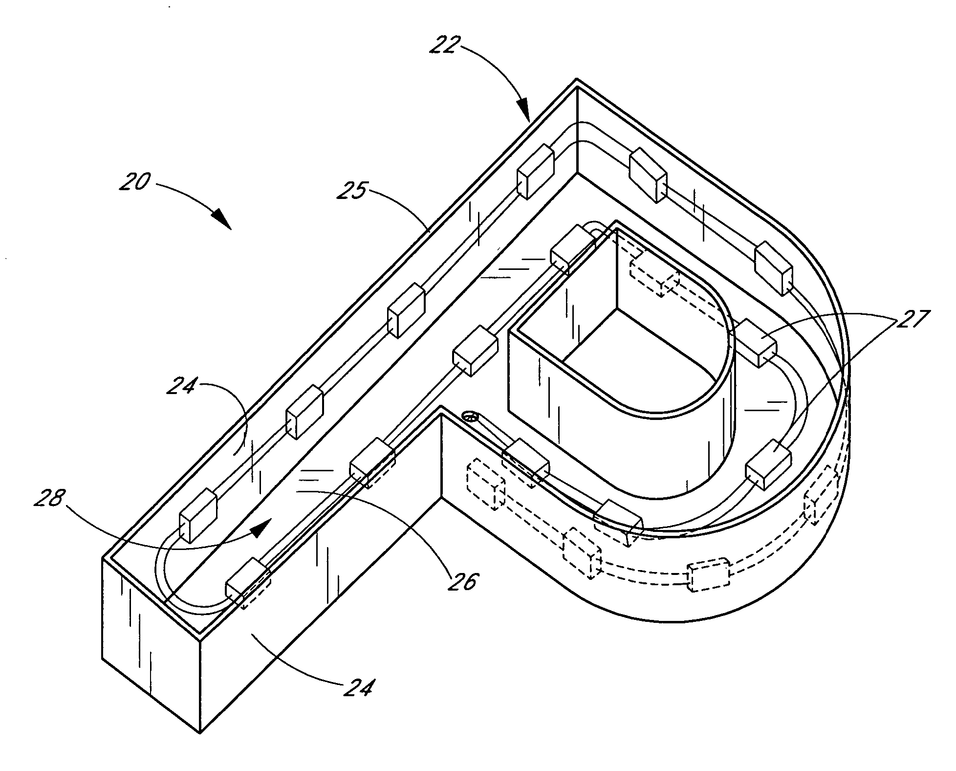
[0028] With reference first to FIG. 1, a channel illumination apparatus 20 is illustrated comprising a casing 22 in the shape of a “P.” The casing 22 includes a plurality of side walls 24 and a back 26, which together define at least one channel 28. The surfaces of the walls 24 and back 26 are diffusely-reflective, preferably being coated with a flat white coating. The walls 24 and back 26 are preferably formed of a durable sturdy metal material. In the illustrated embodiment, a plurality of LED lighting modules 27 are mounted to the walls 24 and back 26 of the casing 22 in a spaced-apart manner. A translucent light-diffusing cover (not shown) is preferably disposed on a front edge 25 of the walls 24 and encloses the channel 28.

[0029] Embodiments of channel illumination apparatuses and LED lighting modules for use therein are described in Applicant's U.S. Pat. No. 6,712,486, issued Mar. 30, 2004, entitled “Mounting Arrangement for Light Emitting Diodes,” and U.S. Pat. No. 6,578,986...


PUM

PropertyMeasurementUnit
sizesaaaaaaaaaa
sizesaaaaaaaaaa
temperatureaaaaaaaaaa

Abstract

An illumination apparatus is provided having a panel including a plurality of circuit units on a dielectric surface. The circuit units include electrically conductive traces and at least one light emitting diode (LED). At least some of the circuit units have contacts for supplying power to the LED. The circuit units are preferably electrically interconnected so that power provided to one circuit unit also supplied power to at least a group of the circuit units. The apparatus with the circuit units may be cut or shaped to a predetermined or desired shape. Also provided are methods of manufacturing, assembling, and using the illumination apparatus.

Description

Related Application [0001] This application claims priority from U.S. Provisional Application No. 60 / 569,814, filed May 10, 2004, entitled “CUTTABLE ILLUMINATED PANEL,” the entirety of which is incorporated herein by reference.BACKGROUND OF THE INVENTION [0002] 1. Field of the Invention [0003] This application is in the field of illumination devices and more particularly in the field of illumination devices employing light emitting diodes (LEDs). [0004] 2. Description of the Related Art [0005] Most lighting applications utilize incandescent or gas-filled bulbs, particularly lighting applications that require more than a low level of illumination. Such bulbs typically do not have long operating lifetimes and thus require frequent replacement. Gas-filled tubes, such as fluorescent or neon tubes, may have longer lifetimes, but operate using dangerously high voltages and are relatively expensive. Further, both bulbs and gas-filled tubes consume substantial amounts of power. [0006] In co...

Claims


Application Information

Patent Timeline
Patent Type & Authority Applications(United States)
IPC IPC(8): G06F1/18G06F1/26G09F9/33G09F13/22
CPCG06F1/189Y10T29/4913G09F13/22G09F9/33
Inventor LYNCH, MANUELFRAITAG, LEONARD
Owner DIAMOND CREEK CAPITAL LLC
Why Eureka
Try Eureka