
Pale

Pending Publication Date: 2022-05-12
HADLEY IND OVERSEAS HLDG LTD
View PDF18 Cites 1 Cited by
  • Summary
  • Abstract
  • Description
  • Claims
  • Application Information

AI Technical Summary

Benefits of technology

The invention provides a new type of pale that is stronger and lighter than previous versions. The pales can be made from less material, without sacrificing their strength, and can be used in the same quantity as previous versions. This results in significant material savings and reduced costs.

Problems solved by technology

However, it is not usually practical to do so.
The use of large quantities of metal in palisade fences 1 results in fencing which can be financially expensive as well as negatively impacting the environment.

Method used


Image

  • Pale
  • Pale
  • Pale

Examples


Embodiment Construction

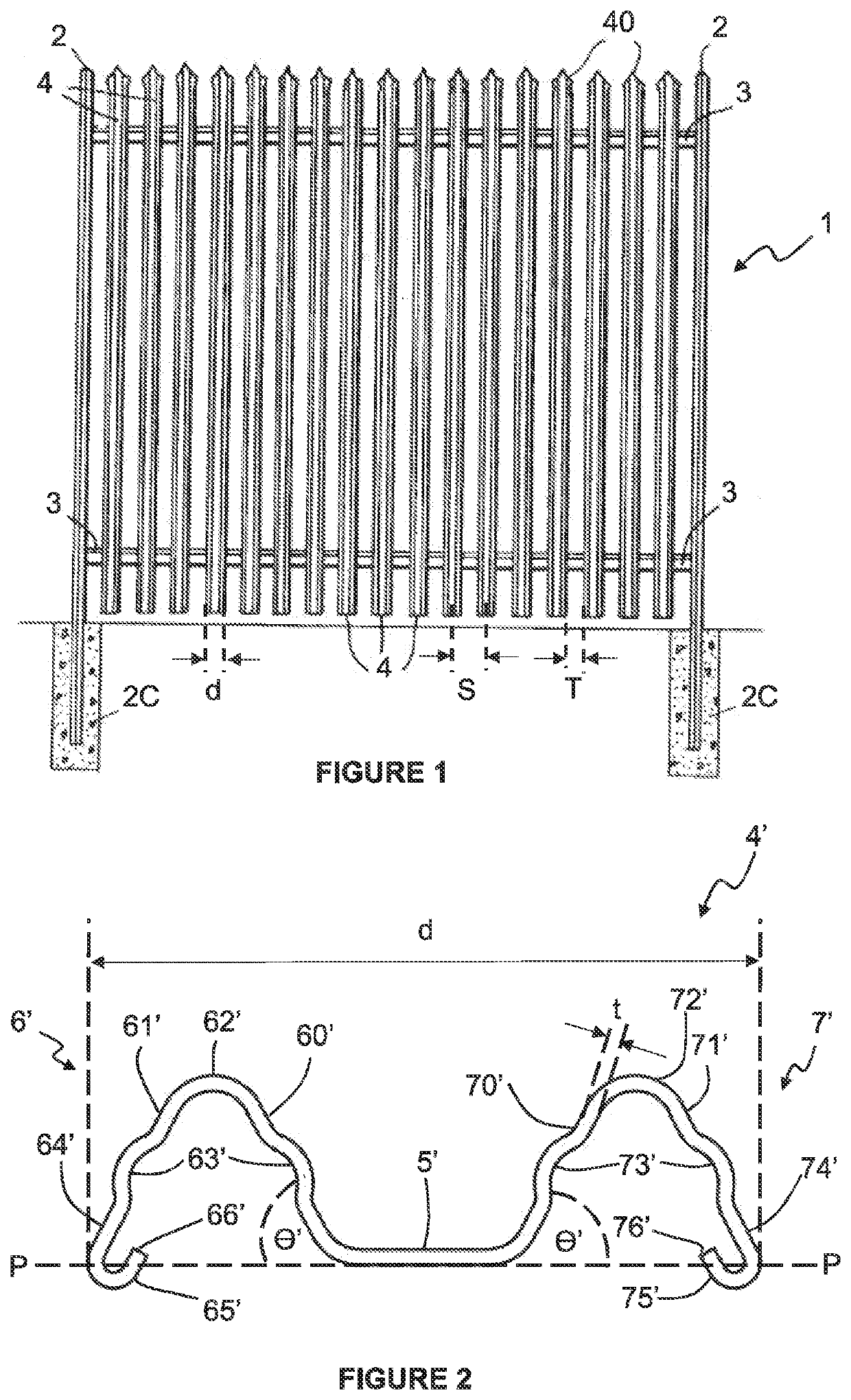
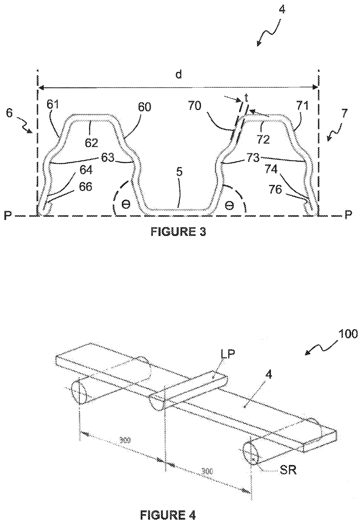
[0052]Referring now to FIG. 2, there is shown a prior art W-shaped pale 4′ which was cold roll formed from a steel strip of width 112.77 mm and thickness t of 1.85 mm. The pale 4′ includes a substantially flat, longitudinal central web 5′ with first and second longitudinal side portions 6′, 7′ projecting from either side of the central web 5′ at an angle θ′ of 62°. The formed pale 4′ has a face to view d of 65.00 mm and is commercially available from Hadley Industries PLC as UltraPALE®200.

[0053]The first longitudinal side portion 6′ includes first and second longitudinal side walls 60′, 61′ connected to one another by an arched, further longitudinal web 62′ extending between respective proximate longitudinal edges. Longitudinally extending corrugations 63′ are included at the midpoint of the first and second longitudinal side walls 60′, 61′. A free, longitudinal edge portion 64′ of the second, longitudinal side wall 61′ extends beyond a plane P defined by the substantially flat, lon...


PUM


Abstract

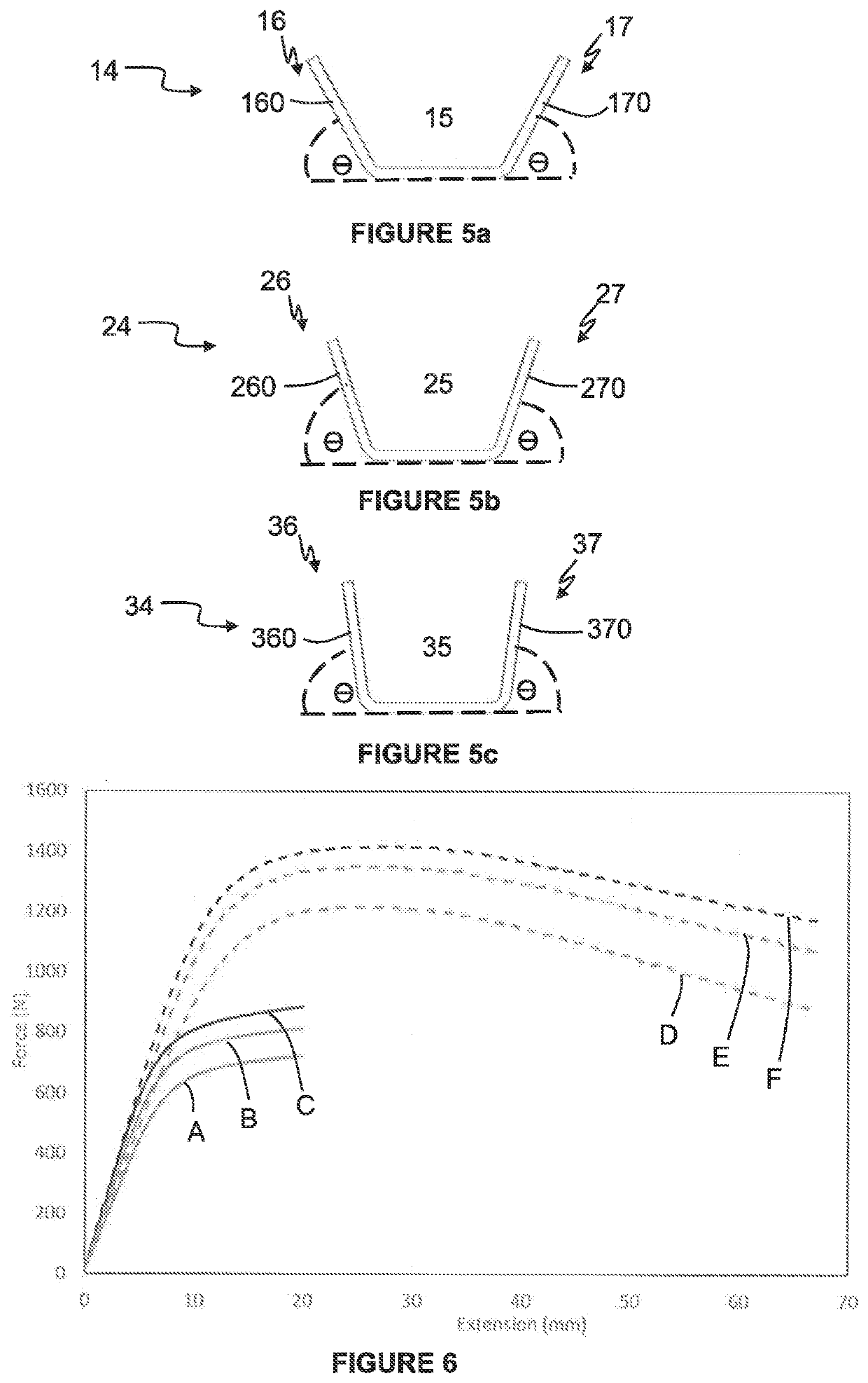
A pale (4) for a palisade fence, the pale (4) comprises a longitudinal web (5) and two longitudinal side portions (6, 7), respective first and second longitudinal side portions (6, 7) extending from each side of the longitudinal web (5) at an angle greater than 70 degrees and less than or equal to 90 degrees.

Description

BACKGROUND OF THE INVENTIONField Of Invention[0001]This invention relates to a pale. More specifically, although not exclusively, this invention relates to a pale for use in a palisade fence and to a fence (e.g. a palisade fence) comprising at least one such pale.Description of Related Art[0002]It is known to build palisade fences in order to prevent access to an area by unauthorised persons. Palisade fences 1 tend to include spaced apart posts 2 joined by horizontal rails 3 to which pales 4 are attached (as shown in FIG. 1). The posts 2 tend to be supported in concrete 2C, while the pales 4 often have security heads 40 at their free, uppermost end. One important consideration of palisade fence design and manufacture is to ensure that the gaps T between individual adjacent pales 4 are small enough to ensure the security of the fence. The size of each gap T is a function of the so called “face to view” d of the pales 4 and the centre-to-centre spacing S between adjacent pales 4 (i.e....

Claims


Application Information

Patent Timeline
IPC IPC(8): E04H17/16E04H17/14
CPCE04H17/166E04H17/143
Inventor CASTELLUCCI, MICHAEL
Owner HADLEY IND OVERSEAS HLDG LTD
Learn More