
Monitoring device, monitoring system, method, computer program and machine-readable storage medium

a monitoring system and monitoring device technology, applied in the field of monitoring devices, can solve the problems of difficult to recognize people easily and reliably, high intra-person variance, and conventional facial recognition methods, and achieve the effect of improving recognition and robust recognition

Pending Publication Date: 2022-05-12
ROBERT BOSCH GMBH
View PDF0 Cites 0 Cited by
  • Summary
  • Abstract
  • Description
  • Claims
  • Application Information

AI Technical Summary

Benefits of technology

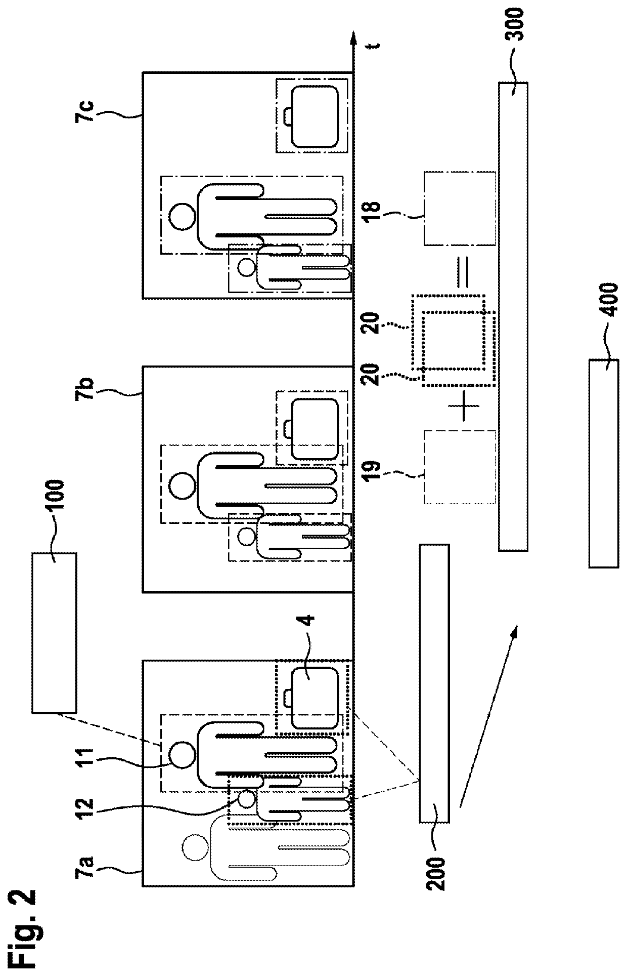
The invention is about an apparatus that combines feature vectors of a person and nearby objects to create a combined feature vector that can better recognize the person and the surrounding objects. This is achieved by adding entries of the person's features to the entries of the nearby objects. This expands the search for the person and makes recognition more robust by taking into account not only the specific properties of the person but also the properties of the surrounding objects. This invention aims to improve recognition in monitoring areas.

Problems solved by technology

Based on the low resolution, however, it is often difficult to recognize people easily and reliably, since conventional facial recognition methods are in this case often susceptible to errors.
Other problems that arise in person recognition in such video recordings are for example high intra-person variance, meaning that for example the same person may look completely different in different cameras.

Method used


Image

  • Monitoring device, monitoring system, method, computer program and machine-readable storage medium
  • Monitoring device, monitoring system, method, computer program and machine-readable storage medium

Examples


Embodiment Construction

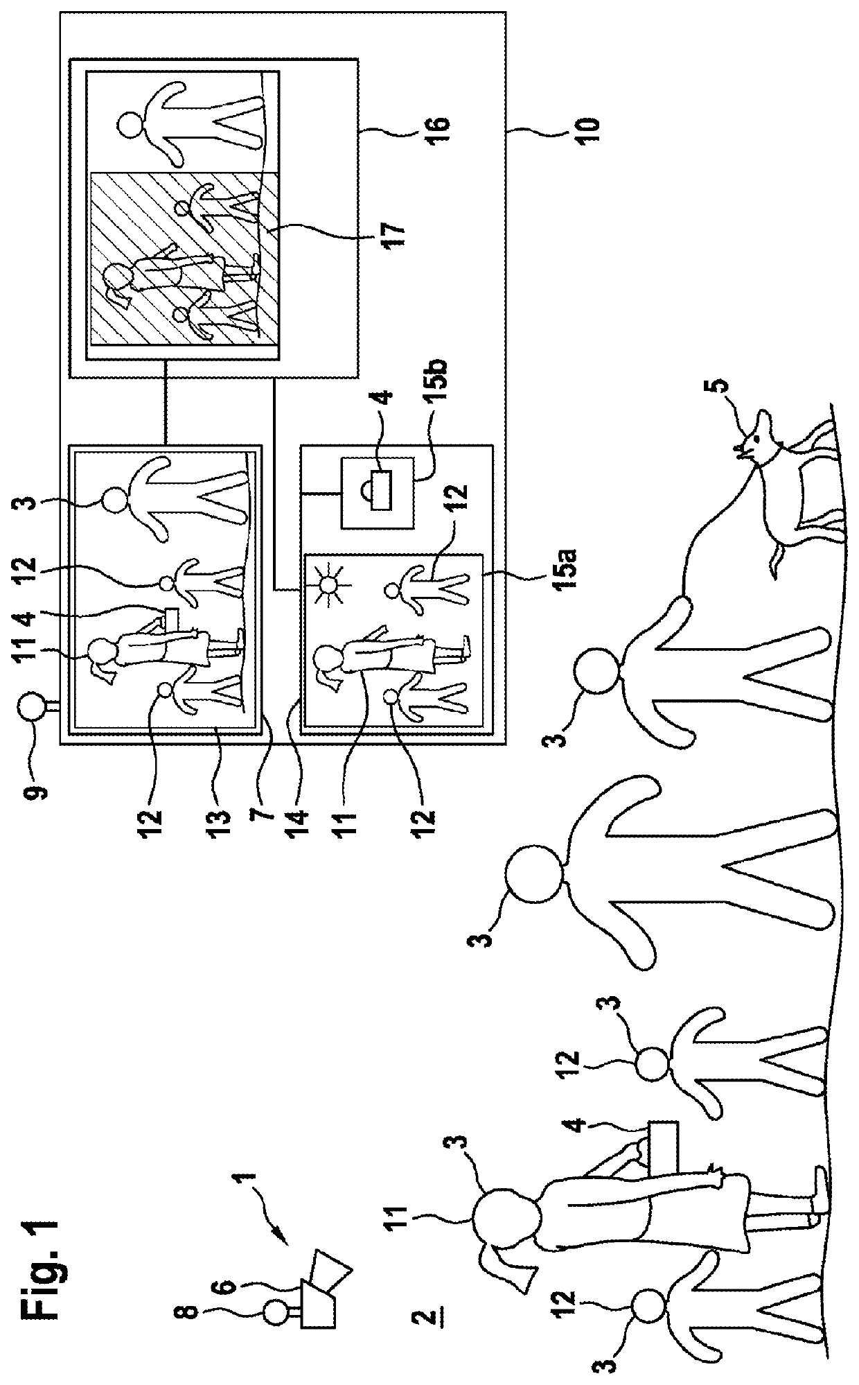
[0027]FIG. 1 schematically shows a monitoring installation 1. The monitoring installation 1 serves to monitor a monitoring area 2. The monitoring area 2 is for example a public building, such as an airport. Multiple and / or a large number of people 3 are moving in the monitoring area 2. The people 3 may be carrying objects, such as for example a case 4 and / or an animal 5. The monitoring area 2 is monitored in terms of video technology by way of at least one camera 6. The monitoring camera 6 provides video data containing monitoring images 7 of the monitoring area 2 and / or a section of the monitoring area. The monitoring images 7 depict the people and objects in monitoring images. The camera 6 has an interface 8 for data-based coupling to a further interface 9. The further interface 9 is encompassed by the monitoring device 10. The monitoring device 10 may for example form a computer unit. By way of example, the monitoring device 10 is part of a central security and / or video monitorin...


PUM


Abstract

The invention relates to a monitoring device (10) for recognizing persons in a monitoring region (2), the monitoring region (2) being video-monitored by means of at least one camera (6) and the camera (6) being designed to provide monitoring images (7) to the monitoring device (10) as video data, the monitoring device comprising: —a feature determination apparatus (13), the feature determination apparatus (13) being designed to determine a feature vector (19) for each object in at least one of the monitoring images (7); —a person recognition apparatus (16), the person recognition apparatus (16) being designed to detect in the monitoring images (7) a person to be recognized (11), on the basis of the determined feature vector and / or the determined feature vectors (19) of the feature determination apparatus (13) and / or a combined feature vector (18); —an association apparatus (14), the association apparatus (14) being designed to determine a feature vector (19) for each person to be recognized (11) and each associated environment object of the person to be recognized (11), the association apparatus (14) being designed to determine the combined feature vector (18) on the basis of the feature vector (19) of the person to be recognized (11) and the feature vector or the feature vectors (20) of the associated environment objects.

Description

BACKGROUND OF THE INVENTION[0001]What is proposed is a monitoring device.[0002]Video monitoring is used in many locations and in particular in public spaces, for example train stations or airports. Use is in this case also often made of person recognition in video footage. Since the areas to be monitored are often formed over a large area, in order to reduce the data load, it is necessary to keep the resolution of the cameras low. Based on the low resolution, however, it is often difficult to recognize people easily and reliably, since conventional facial recognition methods are in this case often susceptible to errors. Other problems that arise in person recognition in such video recordings are for example high intra-person variance, meaning that for example the same person may look completely different in different cameras. Concealment and significant differences caused by the lighting of the scene also have to be taken into consideration.[0003]Document DE 10 2008 043 954 A1, whic...

Claims


Application Information

Patent Timeline
Patent Type & Authority Applications(United States)
IPC IPC(8): G06V20/52G06V20/40G06V40/10G06V10/22G06T7/73G06T7/10
CPCG06V20/53G06V20/46G06V40/10G06V10/23G06T2207/30232G06T7/10G06T2207/10016G06T2207/30196G06T7/73G06V20/52
Inventor BLOTT, GREGORREXILIUS, JAN
Owner ROBERT BOSCH GMBH
Learn More