
Sensor bracket structure

a technology of sensor brackets and brackets, which is applied in the direction of machine supports, vehicle components, transportation and packaging, etc., can solve the problems of unsatisfactory mounting position of sensors (such as lenses of image capture devices), damage to sensors, and unfavorable test results of the pendulum position during contact tes

Pending Publication Date: 2022-05-19
HONDA MOTOR CO LTD
View PDF14 Cites 0 Cited by
  • Summary
  • Abstract
  • Description
  • Claims
  • Application Information

AI Technical Summary

Benefits of technology

The disclosure is about a sensor bracket structure that can protect external sensors from damage and off-centering. This ensures better quality and reduces the need for additional parts.

Problems solved by technology

In the design of the conventional frame component, the mounting position of the sensor (such as a lens of an image capturing device) mounted through a post-process is not satisfactory.
However, since the mounting position of the frame component and the mounting angle of the sensor are not satisfactory, when the frame component is hit by a pendulum during a contact test, the unsatisfactory mounting angle of the sensor leads to unfavorable test results such as an offset axis of the sensor or even damages to the sensor.
Therefore, if the mounting position of the frame component or the mounting angle of the sensor is not satisfactory, the test results with respect to the pendulum position during the contact test may be unfavorable.
As a result, the sensor may be damaged, or the axis of the sensor may be offset.

Method used


Image

  • Sensor bracket structure
  • Sensor bracket structure
  • Sensor bracket structure

Examples


Embodiment Construction

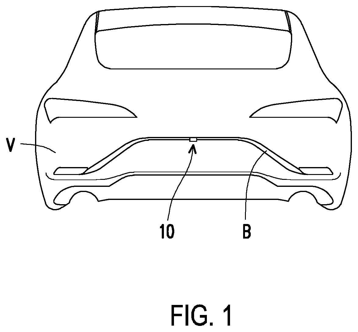
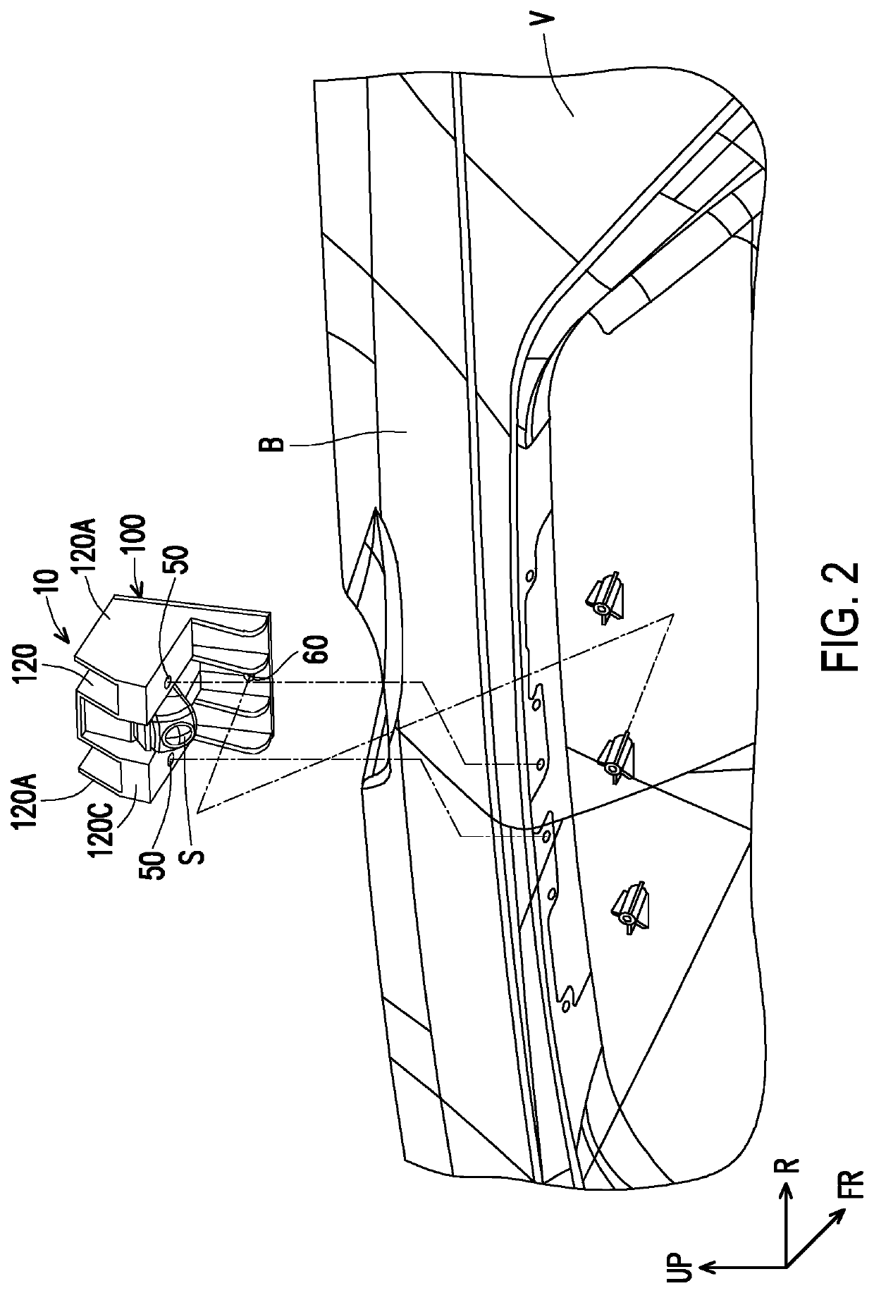
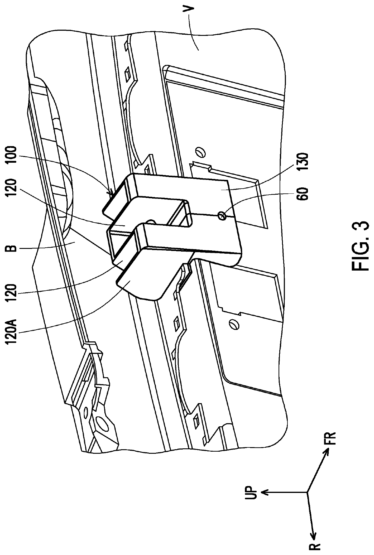
[0023]The disclosure provides a sensor bracket structure capable of suppressing a damage or an axial offset, etc., of an external sensor. Thus, the protection for the external sensor can be reinforced. Accordingly, according to the disclosure, the quality of the sensor bracket structure can be improved without increasing the number of parts.

[0024]According to an aspect of the disclosure, a sensor bracket structure is provided. The sensor bracket structure is adapted to mount an external sensor to a moving body via a bracket. The bracket includes a fixing surface and a load receiving surface connected to the fixing surface. The external sensor is fixed to the fixing surface. The load receiving surface extends from the fixing surface toward the top in a direction where the load receiving surface intersects with the fixing surface. The load receiving surface extends from an outermost side of the external sensor toward the outside.

[0025]Consequently, in the sensor bracket structure of t...


PUM


Abstract

The disclosure provides a sensor bracket structure adapted to mount an external sensor to a moving body via a bracket. The bracket includes a fixing surface and a load receiving surface connected to the fixing surface. The external sensor is fixed to the fixing surface. The load receiving surface extends from the fixing surface toward the top in a direction where the load receiving surface intersects with the fixing surface. The load receiving surface extends from an outermost side of the external sensor toward the outside.

Description

CROSS-REFERENCE TO RELATED APPLICATION[0001]This application claims the priority benefit of Chinese application serial no. 202022656425.1, filed on Nov. 17, 2020. The entirety of the above-mentioned patent application is hereby incorporated by reference herein and made a part of this specification.BACKGROUNDTechnical Field[0002]The disclosure relates to a sensor bracket structure.Description of Related Art[0003]In recent years, various image capturing devices, sensors, etc., have been attached to various parts of various transportation means, such as automobiles, loaders, and the amount of vehicles using sensors to acquire external information have been increasing. Sensors, such as millimeter wave radars, for acquiring external information are usually mounted inside the front / rear bumper of a vehicle and external components near the bumper. Such sensor is usually supported by a metal sensor bracket, and the sensor bracket is attached to a frame component of the vehicle body, etc.[00...

Claims


Application Information

Patent Timeline
IPC IPC(8): F16M13/02B60R11/04
CPCF16M13/02B60R2011/004B60R11/04B60R2011/0045
Inventor OGURI, MASAYUKIGEMBA, YOSHINORITSUBURAOKA, DAISUKEMATSUMOTO, SHINYAHIDAKA, YU
Owner HONDA MOTOR CO LTD
Learn More