
Touch panel device, operation identification method, and storage medium storing operation identification program

Pending Publication Date: 2022-05-19
MITSUBISHI ELECTRIC CORP
View PDF0 Cites 1 Cited by
  • Summary
  • Abstract
  • Description
  • Claims
  • Application Information

AI Technical Summary

Benefits of technology

The present invention provides a touch panel device with high operability. It uses an operation identification method and program to accurately determine whether a touch operation is a normal touch operation or a depressing operation, thereby increasing the operability of the touch panel.

Problems solved by technology

However, there are cases where this touch panel device erroneously judges a touch operation performed intending the normal touch operation as the depressing operation or erroneously judges a touch operation performed intending the depressing operation as the normal touch operation.
However, since the touch panel device described in the Patent Reference 1 sets the threshold value for the judgment on the depressing operation in regard to each of the predetermined regions, the touch panel device can make an erroneous judgment on whether a touch operation is a normal touch operation or a depressing operation in a case where the pressing force threshold value varies in each region and in a case where one operation button extends across a plurality of regions.
There is a problem in that the erroneous judgment deteriorates the operability of the touch panel device.

Method used


Image

  • Touch panel device, operation identification method, and storage medium storing operation identification program
  • Touch panel device, operation identification method, and storage medium storing operation identification program
  • Touch panel device, operation identification method, and storage medium storing operation identification program

Examples


first embodiment

(1) First Embodiment

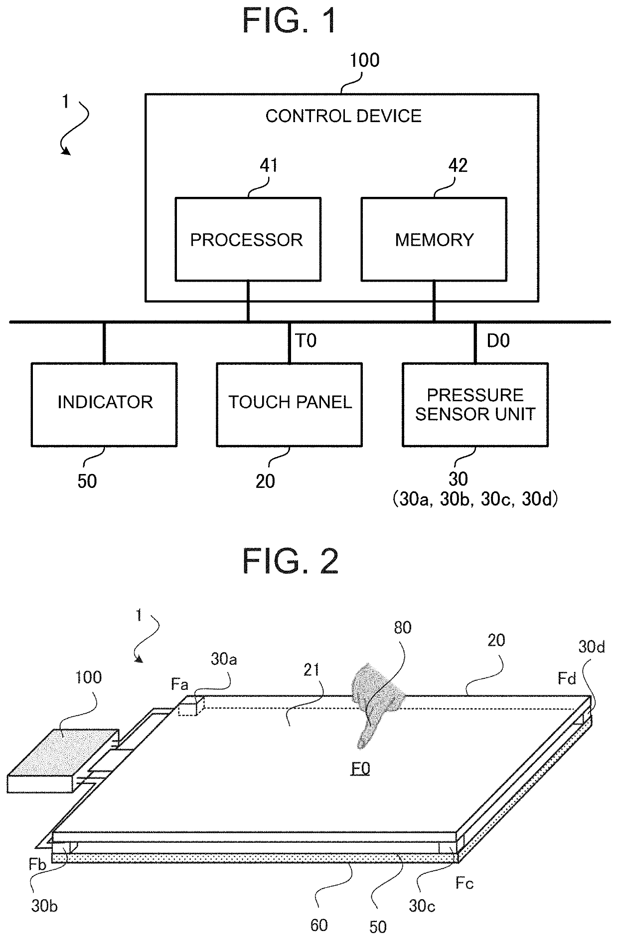
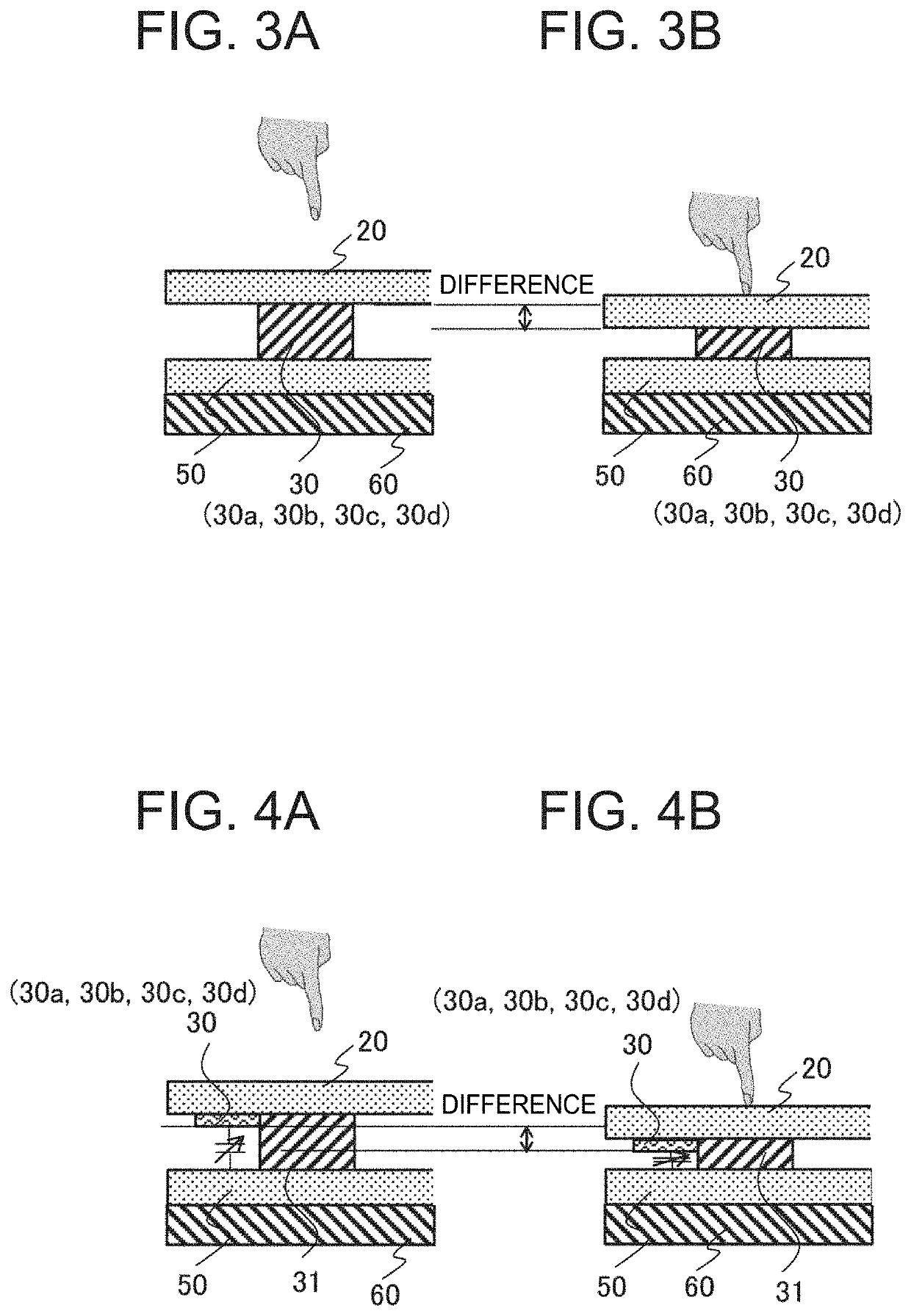
[0033]FIG. 1 is a diagram showing an example of the hardware configuration of a touch panel device 1 according to a first embodiment. As shown in FIG. 1, the touch panel device 1 includes a touch panel 20, a pressure sensor unit 30, a display device 50 and a control device 100. The touch panel 20 has an operation surface on which touch operations are performed by a user. The display device 50 is, for example, a liquid crystal display arranged in superimposition with the touch panel 20. The display device 50 may also be formed integrally with the touch panel 20. The display device 50 is controlled by the control device 100 and displays an operation screen or the like. The operation screen is a user interface (UI) screen including objects as operation components such as icons. The touch panel 20 is, for example, a capacitive touch panel in which electrostatic capacitance of a part of the operation surface in contact with a conductor changes. The touch panel 20 outp...

second embodiment

(2) Second Embodiment

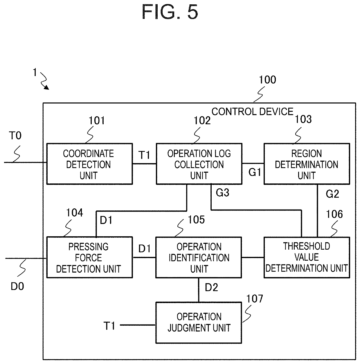
[0098]The touch panel device 1 according to the first embodiment estimates group regions corresponding to operation regions based on operation logs of touch operations performed on the touch panel 20, obtains the frequency distribution of the pressing value in each group region, and updates the depressing operation threshold value based on the obtained frequency distribution. In contrast, a touch panel device 2 according to a second embodiment increases the accuracy of the estimation of the operation regions by using object information indicating objects constituting a GUI (Graphical User Interface) as the UI screen displayed on the display device 50. Here, the objects constituting the GUI are operation components such as icons.

[0099]FIG. 15 is a functional block diagram schematically showing the configuration of the touch panel device 2 according to the second embodiment. In FIG. 15, each component identical or corresponding to a component shown in FIG. 5 is as...

third embodiment

(3) Third Embodiment

[0106]On a touch panel device for an industrial purpose, there are cases where a specific pattern of touch operation is performed repeatedly. Such an operation is referred to as a “flow operation”. The flow operation is frequently performed mainly by users skilled in operations. The flow operation tends to be performed with pressing force different from pressing force in operations other than the flow operation.

[0107]For example, there are cases where the user executes a variety of setting work by successively performing two touch operations on the touch panel device and performs a depressing operation, for making the device incorporate the contents of the setting, multiple times after the completion of the setting work. Since the threshold value is updated by a depressing operation, it is presumed that the threshold value at the time of performing the final depressing operation becomes smaller than an average pressing value of depressing operations. If the depre...


PUM


Abstract

A touch panel device includes processing circuitry to generate coordinate information indicating a position of a touch operation; to generate a pressing value corresponding to pressing force applied to an operation surface of a touch panel; to classify the positions of touch operations included in operation logs each being data including the coordinate information and information indicating the pressing value into groups and to determine group regions respectively corresponding to the groups; to determine a threshold value of the pressing value in each of the group regions based on the operation logs; and to judge that the touch operation is a depressing operation with pressing force if the pressing value is greater than or equal to the threshold value and to judge that the touch operation is a normal touch operation other than the depressing operation if the pressing value is less than the threshold value.

Description

CROSS-REFERENCE TO RELATED APPLICATION[0001]This application is a continuation application of International Application No. PCT / JP2019 / 034687 having an international filing date of Sep. 4, 2019, the disclosure of which is incorporated herein by reference in its entirety.BACKGROUND OF THE INVENTION1. Field of the Invention[0002]The present disclosure relates to a touch panel device, an operation identification method and a storage medium storing an operation identification program.2. Description of the Related Art[0003]A touch panel device having a pressure detection function and capable of detecting the pressing force of a touch operation is in practical use. This touch panel device recognizes a touch operation with pressing force less than a threshold value as a normal touch operation, and recognizes a touch operation with pressing force greater than or equal to the threshold value as a depressing operation (referred to also as a “depressing touch operation”). However, there are ca...

Claims


Application Information

Patent Timeline
IPC IPC(8): G06F3/041
CPCG06F3/0418G06F2203/04105G06F3/04144G06F3/04166G06F2203/04106
Inventor OSAWA, SOHEISASAKI, YUICHIYAMAMOTO, AKIHITOMORI, KENTARO
Owner MITSUBISHI ELECTRIC CORP
Learn More