
Input controller used together with pointing device and input control method

Inactive Publication Date: 2009-12-17
PIONEER CORP
View PDF2 Cites 2 Cited by
  • Summary
  • Abstract
  • Description
  • Claims
  • Application Information

AI Technical Summary

Benefits of technology

[0011]Moreover, such a position shift occurs more easily if the user operates the pointing device with it lifted up by the hand than if the user operates the pointing device with it placed on a desk. For example, if the user operates a remote controller provided with the pointing device (hereinafter referred to as a “remote controller”), the position shift of the pointer easily occurs.
[0013]In view of the aforementioned problems, it is therefore a first object of the present invention to provide an input control apparatus, an input control method, and a computer program, which can prevent a user's intentional process from not being performed because of the displacement of an indication mark such as a pointer and a highlight, generated when a user presses an operation switch, and which can thus increase the operability of a user interface, a pointing device, or an operated apparatus.

Problems solved by technology

Such a situation leads to low operability of the graphic user interface, which is not preferable.

Method used


Image

  • Input controller used together with pointing device and input control method
  • Input controller used together with pointing device and input control method
  • Input controller used together with pointing device and input control method

Examples


first embodiment

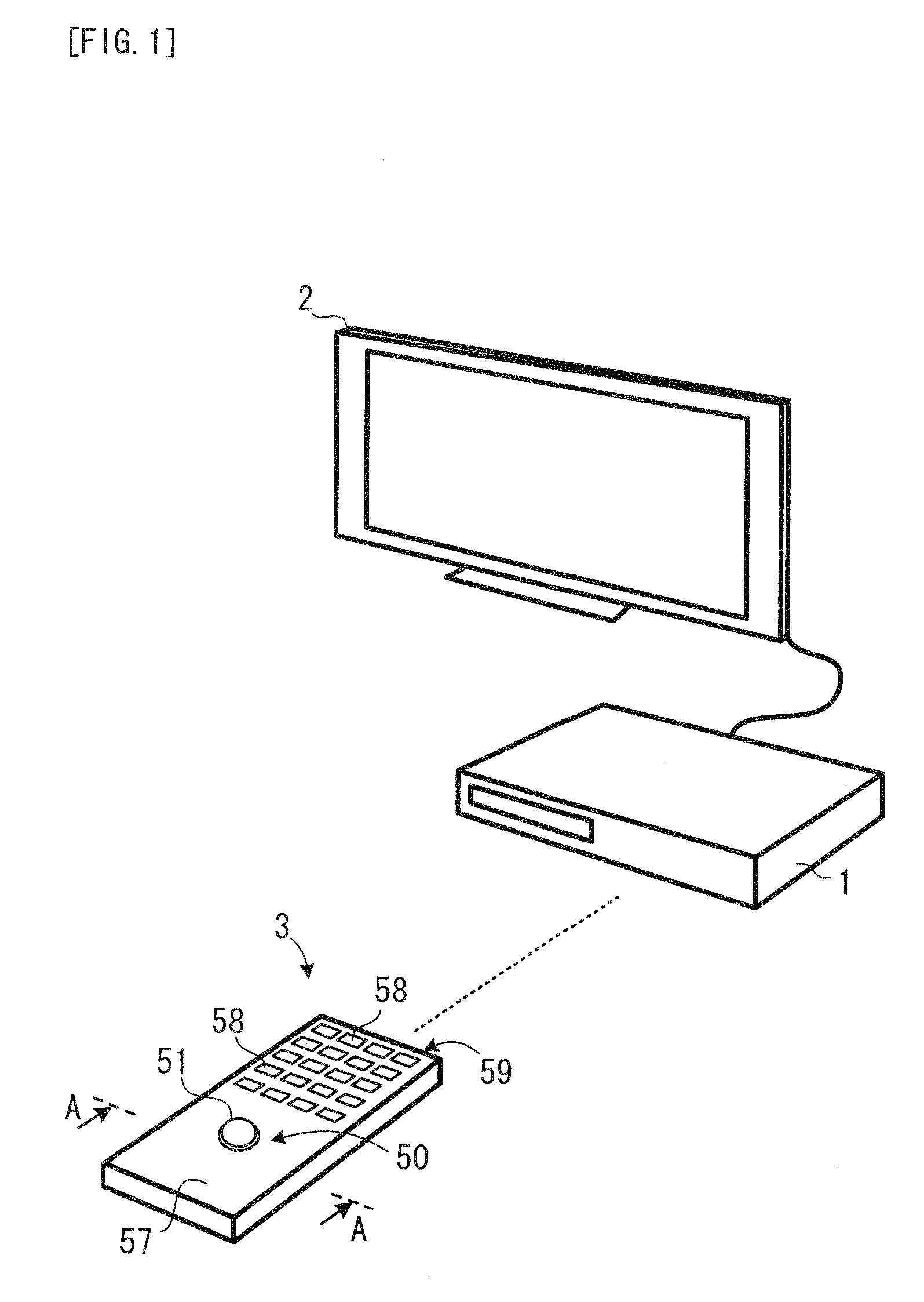
[0049]FIG. 1 shows a recorder, a remote controller, and a display apparatus.

[0050]A recorder 1 in FIG. 1 is a first embodiment of the input control apparatus of the present invention. The recorder 1 is, for example, a hard disk drive recorder with a built-in television tuner. The recorder 1 has a normal function as the recorder: a function of receiving program content data transmitted from a television broadcast station and storing it onto a hard disk. The recorder 1 also has a graphic user interface function for operating the recorder 1. The recorder 1 also has a position shift cancel function described later. Moreover, a display apparatus 2 is connected to the recorder 1.

[0051]A remote controller 3 is an apparatus for remotely operating the recorder 1. The remote controller 3 has a function of wirelessly communicating with the recorder 1 through radio waves and uses the radio waves to remotely control the recorder 1. Moreover, the remote controller 3 is provided with a trackball 5...

second embodiment

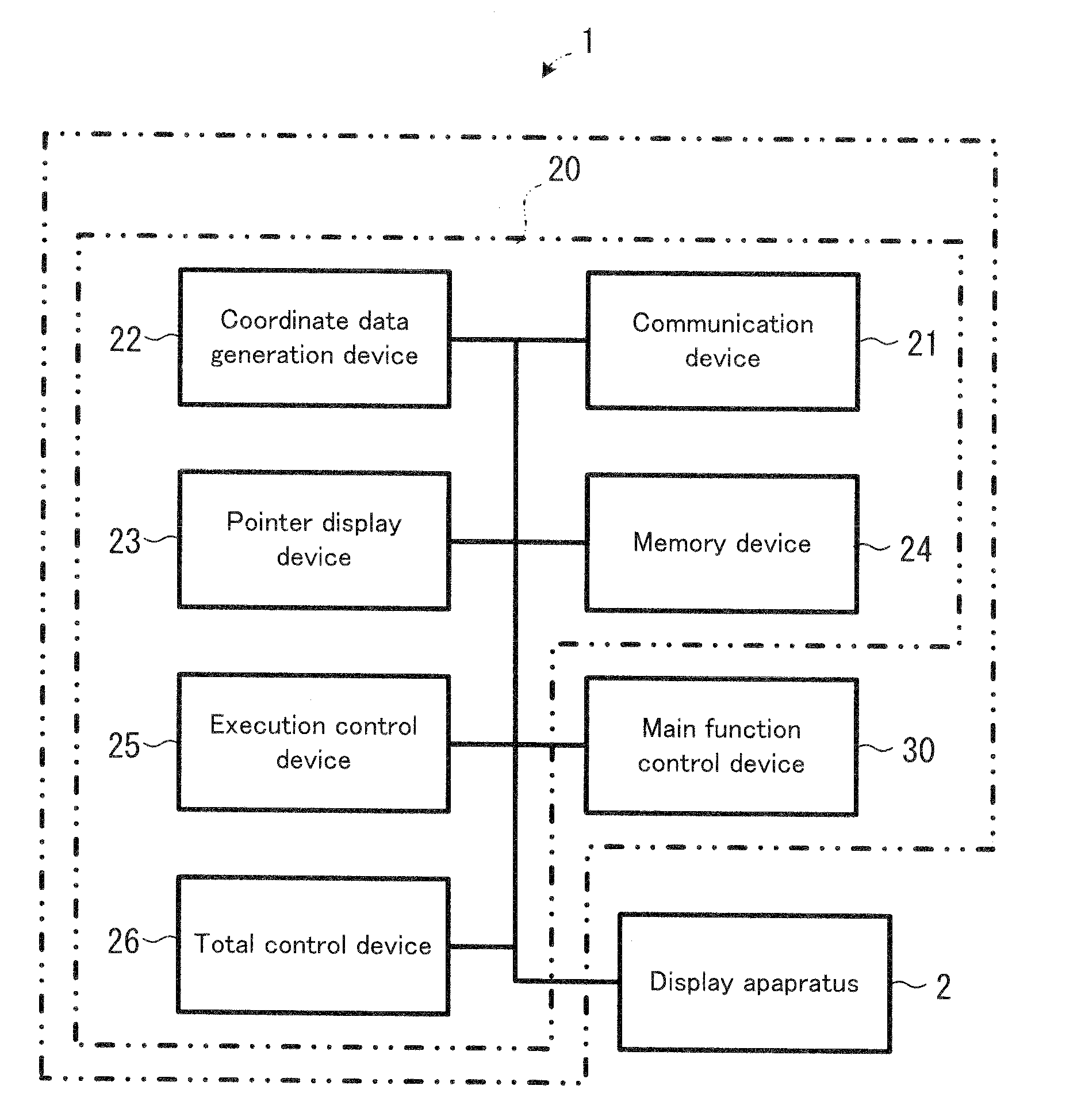
[0109]FIG. 9 shows the inner structure of a recorder, which is a second embodiment of the input control apparatus of the present invention.

[0110]A recorder 70 in FIG. 9 has the position shift cancel function. The method of realizing the position shift cancel function of the recorder 70 is different from that of the recorder 10 in FIG. 4.

[0111]In order to realize the position shift cancel function, the recorder 70 accumulates the coordinate data which indicates the indication position in the screen 2A and displacement velocity data which indicates a displacement velocity of the indication position, in a memory device 85. When the operation switch 54 of the trackball 50 is turned on and thus the operation switch signal is received, the recorder 70 reads the coordinate data generated at a certain time point which is the predetermined retrospective time before the time point that the operation switch signal is received and at which the displacement velocity of the indication position is...


PUM


Abstract

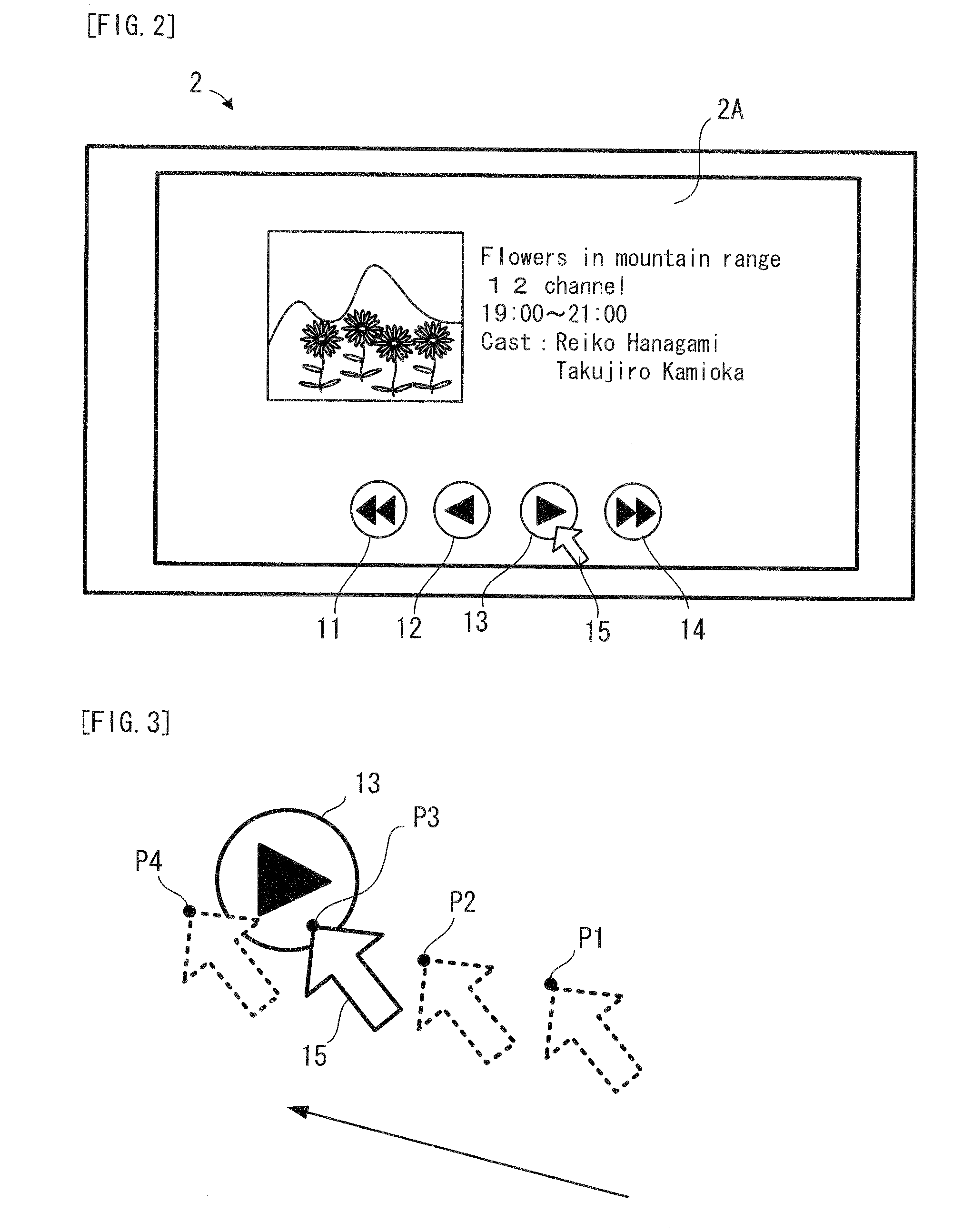
Coordinate data on a position pointed out by a pointer on a screen is stored in a storage section. When a control switch (ball) is depressed, the coordinate data corresponding to a moment before a predetermined time counted substantially from the moment when the control switch is depressed is read from the storage section and a processing associated with the pointed position corresponding to the coordinate data is performed.

Description

TECHNICAL FIELD[0001]The present invention relates to an input control apparatus for and an input control method of displacing a pointer or highlight or the like on a screen in accordance with the operation of a pointing device and performing a process indicated by the pointer or highlight.BACKGROUND ART[0002]A graphic user interface (GUI) is widely used for personal computers. In recent years, the graphic user interface has been also used for AV (Audio-Visual) equipment such as DVD recorders, hard disk drive recorders, and portable music players, a car navigation system, and the like.[0003]The graphic user interface uses a pointing device as an input apparatus. The most popular pointing device is a mouse, but such a pointing device as a trackball, a touch panel, and a joy stick is also common.[0004]In the normal trackball, the ball and the operation switch are separately disposed. Thus, normally, a user sequentially touches the two operation elements, i.e. the ball and the operatio...

Claims


Application Information

Patent Timeline
IPC IPC(8): G06F3/033G06F3/0354
CPCG06F3/03549G06F3/0481G06F3/038
Inventor NAKAMURA, HIROSHI
Owner PIONEER CORP
Learn More