
Walking stick grip

a technology of walking sticks and grips, applied in the field of walking sticks, can solve the problems of loss outweighing convenience, damage to the camera, discomfort to the user,

Active Publication Date: 2022-05-26
CHEN NAI CHING
View PDF8 Cites 1 Cited by
  • Summary
  • Abstract
  • Description
  • Claims
  • Application Information

AI Technical Summary

Benefits of technology

The present invention is a walking stick grip designed to make it easier for hikers to take pictures. It has track slots that can hold the connecting buckle of a photographic device, allowing for easy attachment and detachment of the camera. The grip also has a cover body with a fastener that can be easily mounted on the grip for easy gripping. Overall, this invention improves the hiking and picture-taking experience.

Problems solved by technology

When so placed, however, the selfie stick is very likely to fall off or collide with other objects during hiking and thus cause damage to the camera mounted on the selfie stick, which if happening will be a loss outweighing the convenience of carrying the selfie stick on or near the user's waist.
In addition, inserting the selfie stick in the loop formed by the fixing strap on the user's waist may cause discomfort to the user.

Method used


Image

  • Walking stick grip
  • Walking stick grip
  • Walking stick grip

Examples


first embodiment

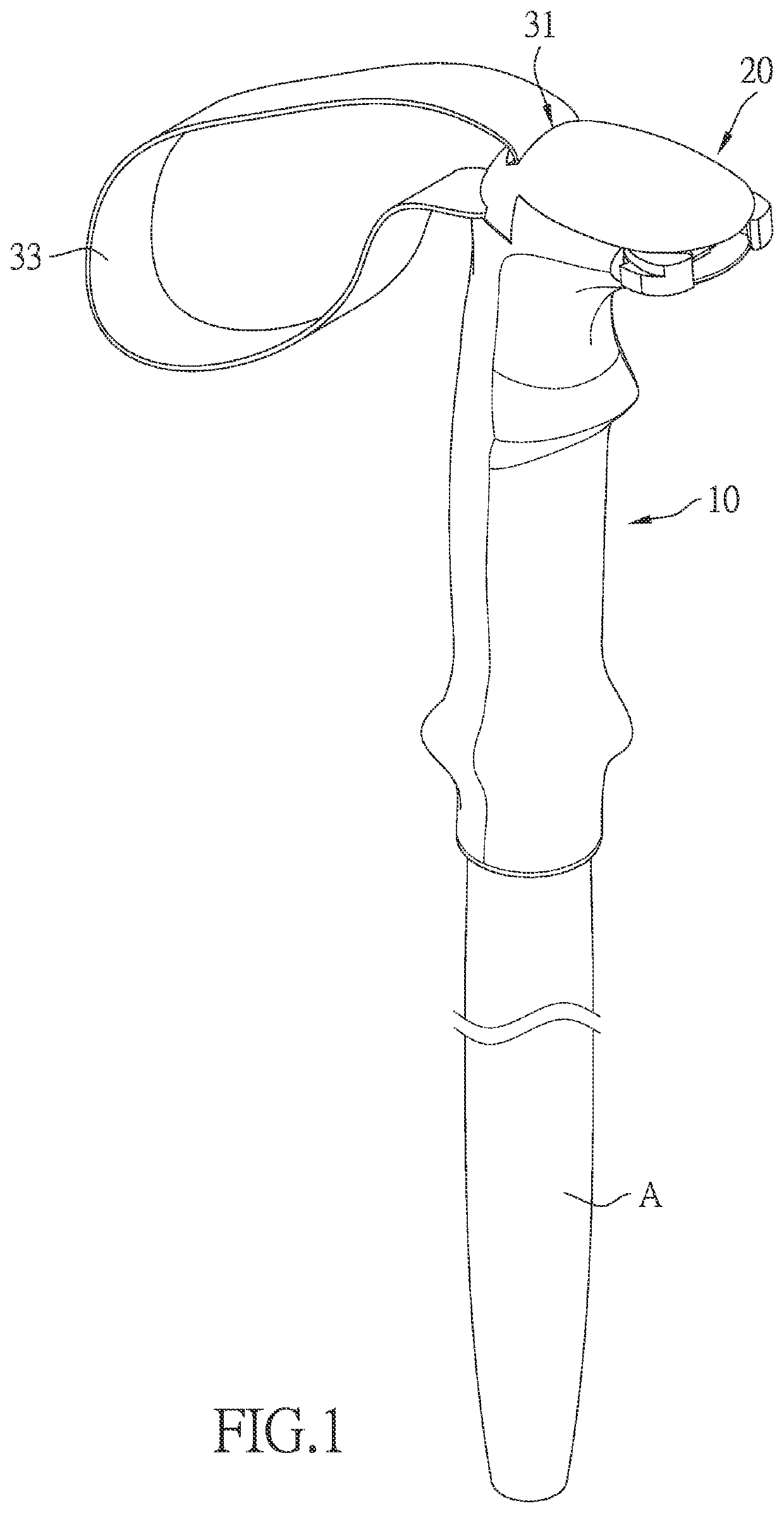
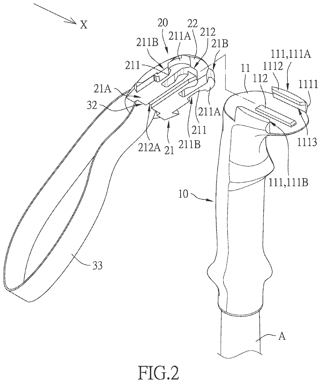
[0021]According to the present invention, referring to FIG. 1 and FIG. 2, the grip cover 22 has a first insertion hole 31, and the fastener 21 has a second insertion hole 32. There is also a first grip strap 33, and the first grip strap 33 is inserted through the first insertion hole 31 and the second insertion hole 32. The first grip strap 33 is in the shape of a loop and is configured to be held by the user.

second embodiment

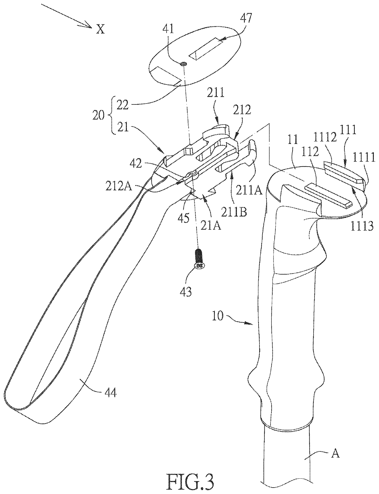
[0022]According to the present invention, referring to FIG. 3 and FIG. 4, the grip cover 22 has a first locking hole 41, and the fastener 21 has a second locking hole 42. There is also a threaded locking member 43, and the threaded locking member 43 is passed through the second locking hole 42 and locked in the first locking hole 41 such that the grip cover 22 and the fastener 21 are connected together.

[0023]In the second embodiment, there is also a second grip strap 44, and the fastener 21 further has a third insertion hole 45. The second grip strap 44 is inserted through the third insertion hole 45, is in the shape of a loop, and is configured to be held by the user.

[0024]In the second embodiment, the side of the fastener 21 that faces the grip cover 22, i.e., the second side 21B, has a first engaging block 46, and the side of the grip cover 22 that faces the fastener 21 has a first engaging recess 47. The first engaging block 46 is fixedly engaged in the first engaging recess 47....

third embodiment

[0025]According to the present invention, referring to FIG. 5 and FIG. 6, the fastener 21 has a first fitting block 51 and a through groove 52. The through groove 52 extends through the fastener 21. The through groove 52 has two opposite groove openings respectively defined as a first groove opening 521 and a second groove opening 522. The first groove opening 521 faces the grip cover 22. The second groove opening 522 faces the connecting end face 11. The through groove 52 is adjacent to the first fitting block 51. The through groove 52 is provided therein with a fixing block 53. The fixing block 53 is a generally rectangular block. There is also a third grip strap 54, and the third grip strap 54 has one end fixed to the first fitting block 51, extends out of the through groove 52 through the second groove opening 522, reenters the through groove 52 through the second groove opening 522 while surrounding the fixing block 53, and then extends out of the second groove opening 522 agai...


PUM


Abstract

A walking stick grip is defined with track slots for receiving a connecting buckle of a photographic device and with a convex portion engageable in a sliding groove of the connecting buckle and hence connectable to the photographic device. After taking pictures with the photographic device connected to the walking stick grip, the photographic device can be detached, and a cover body can be mounted on the grip, with the convex portion received in a sliding groove of the cover body, and convex sections of the cover body respectively pressed against blocking portions of the grip so that the portion of the grip that is mounted with the cover body can be gripped. The walking stick grip, therefore, facilitates picture taking as well as hiking.

Description

BACKGROUND OF THE INVENTION1. Technical Field[0001]The present invention relates to a walking stick and more particularly to the grip structure of a walking stick.2. Description of Related Art[0002]Walking sticks for use in hiking, also known as trekking poles, have become essential equipment in hiking activities because they can help a user exert a pushing force when the user is going uphill and help support the user when the user is going downhill, thereby allowing the user to make good use of their limbs and reducing the load on the user's knees. If, however, a hiker walking with the assistance of the trekking pole in each hand wishes to take a selfie when in sight of a beautiful mountain, the trekking poles must be put down before the hiker can take a selfie stick from inside their backpack or from a side pocket of the backpack, mount a camera on the selfie stick, and take the selfie. Moreover, once the selfie is taken, the hiker may not know where to put the selfie stick to fac...

Claims


Application Information

Patent Timeline
IPC IPC(8): A45B9/02
CPCA45B9/02A45B2009/002A45B2200/05A45B2009/025A45B3/00
Inventor CHEN, NAI-CHING
Owner CHEN NAI CHING
Learn More